
Hub bearing cage assembly press-fitting device

A technology of wheel hub bearings and press-fitting devices, which is applied to bearing components, shafts and bearings, mechanical equipment, etc., can solve the problems of reduced production efficiency, increased labor costs, inconvenience, etc., and achieves fast speed, high installation efficiency, and improved production efficiency Effect

Active Publication Date: 2019-08-06
广德中隆轴承有限公司
View PDF4 Cites 0 Cited by
  • Summary
  • Abstract
  • Description
  • Claims
  • Application Information

AI Technical Summary

Problems solved by technology

[0002] Existing hub bearings are composed of multiple inner rings that require multiple cage assemblies. Generally, only one cage assembly can be pressed into one side at a time, so it is basically manual work, which not only increases labor costs, but also slows down the efficiency. , very inconvenient, greatly reducing production efficiency

Method used


Image

  • Hub bearing cage assembly press-fitting device
  • Hub bearing cage assembly press-fitting device
  • Hub bearing cage assembly press-fitting device

Examples


Embodiment 1

[0052] The first-generation hub bearing press-fitting process is as follows:

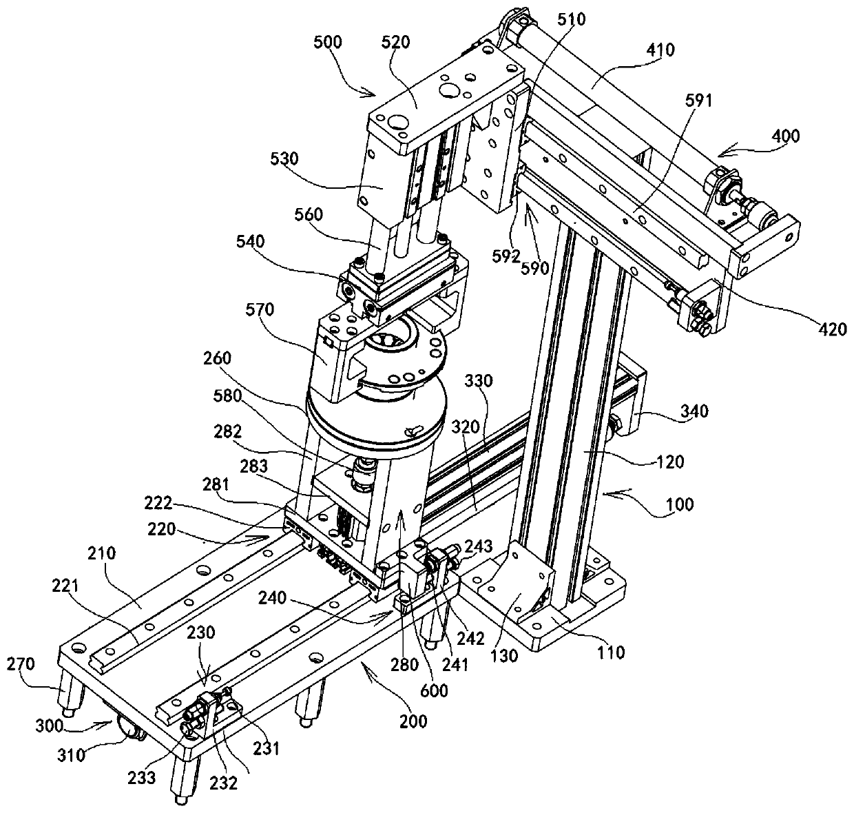
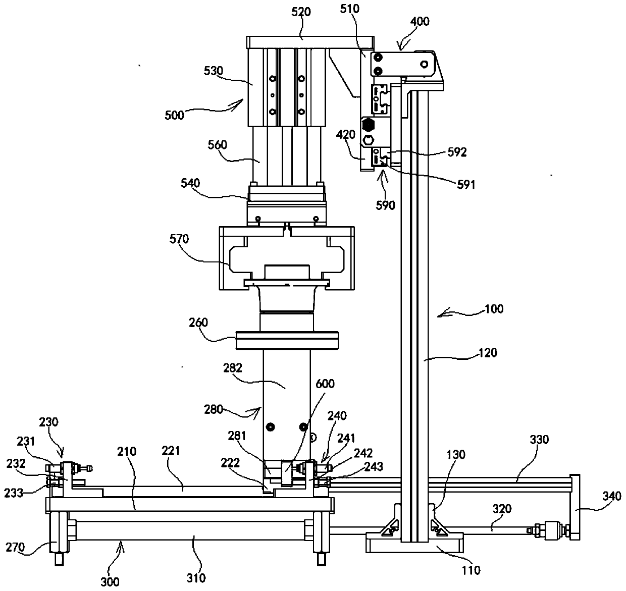
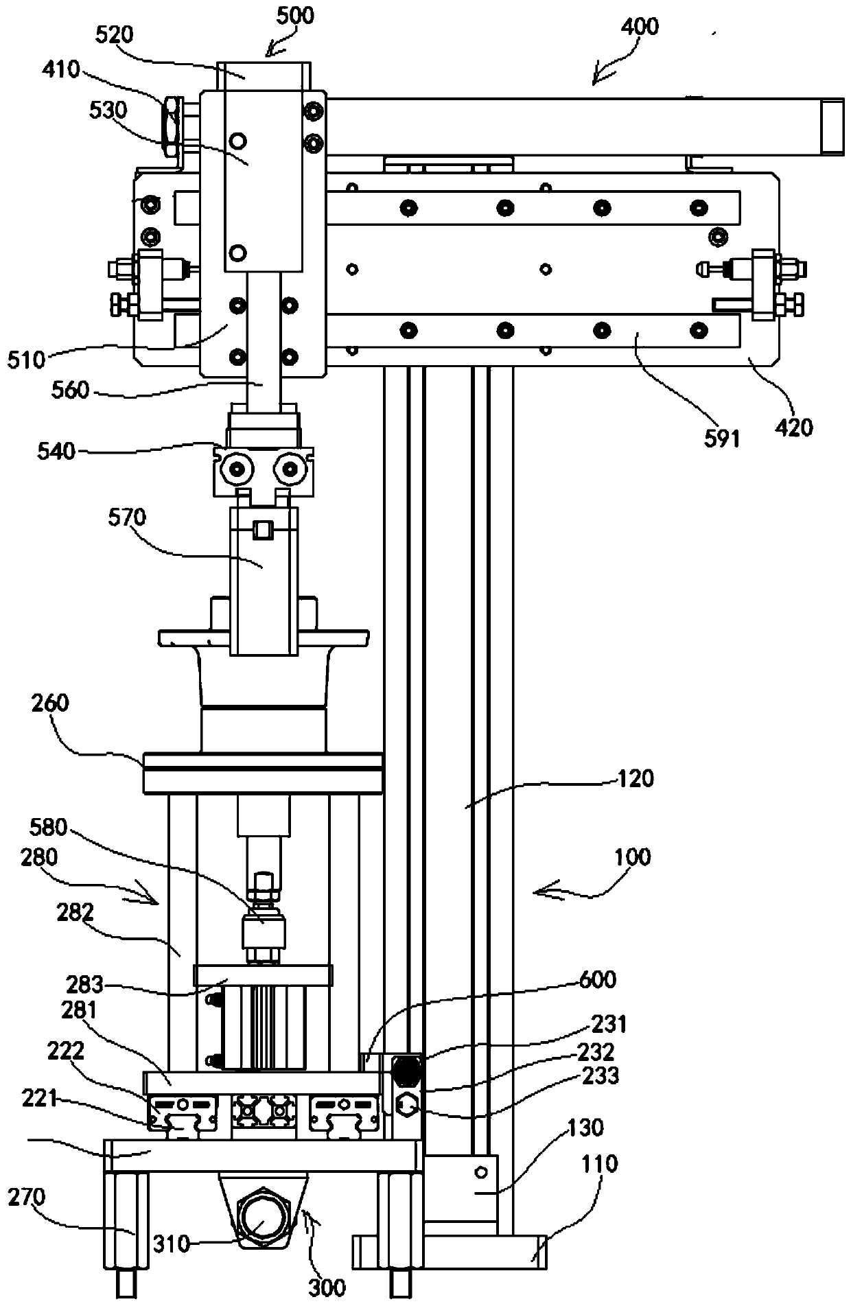
[0053] A feeding device puts two sets of cage assemblies on the workbench behind the two sides of the ferrule on the workbench, and the stretching cylinder pushes out the connecting plate, thereby driving the push rod, so that the first slider under the supporting and fixing device moves along the guide rail , until the second buffer device, the lifting cylinder will pass through the lifting cylinder joint and connecting rod, according to the direction of the guide sleeve, push the cage assembly on the lower mold to the designated position inside the ferrule and fix it, and at the same time, the clamping cylinder will go down and clamp 1 The first-generation wheel hub bearing, and the upper pressure block fixed on the lower part of the clamping cylinder presses the cage assembly on the other side to the designated position inside the ferrule, and completes the simultaneous pressing of the cage assemb...

Embodiment 2

[0055] The press-fitting process of the second-generation hub bearing is as follows:

[0056] A feeding device puts the outer ring on the lower mold of the workbench, puts the positioning block in the outer ring, then puts the cage and steel balls, and then presses them in; the stretching cylinder pushes out the connecting plate, drives the push rod, and makes The first slider under the support and fixing device moves to the second buffer device along the guide rail; the lifting cylinder moves in the direction of the guide sleeve through the connecting head and connecting rod of the lifting cylinder, and pushes the cage assembly on the lower mold to the inside of the ferrule. The specified position is fixed, and at the same time, the lifting cylinder controls the clamping cylinder to descend to clamp the second-generation hub bearing. When it is placed and pressurized, the outer ring falls off; when the clamping mechanism exits the ferrule, the stretching cylinder pulls back th...


PUM


Abstract

The invention discloses a hub bearing cage assembly press-fitting device. The hub bearing cage assembly press-fitting device comprises a bottom frame and a bracket, wherein the bracket further comprises a supporting base and a supporting stand column, a supporting plate on which a first slide assembly, a first buffer device, a second buffer device, a first drive device and a workbench are placed is arranged on the bottom frame; a second drive device and a clamping lifting device are mounted on the bracket; and the first slide assembly and a second slide assembly are separately arranged on the bottom frame and the bracket. When the hub bearing cage assembly press-fitting device can be independently used, a plurality of cage assemblies of a hub bearing can be simultaneously pressed in; when the hub bearing cage assembly press-fitting device is matched with a connecting line (automatic production line) for use, automation is provided for equipment; and the hub bearing cage assembly press-fitting device is high in mounting efficiency and is high in speed, so that production efficiency is greatly improved.

Description

technical field [0001] The invention relates to the field of wheel hub bearing press-fitting, in particular to a wheel hub bearing cage assembly press-fitting device. Background technique [0002] Existing hub bearings are composed of multiple inner rings that require multiple cage assemblies. Generally, only one cage assembly can be pressed into one side at a time, so it is basically manual work, which not only increases labor costs, but also slows down the efficiency. , very inconvenient, greatly reducing production efficiency. Contents of the invention [0003] The purpose of the present invention is to overcome the deficiencies of the prior art and provide a press-fitting device for hub bearing cage components, which can realize simultaneous pressing of multiple cage components of hub bearings when used alone, and can provide equipment with a matching connection. Automation, its installation efficiency is high, and its speed is fast, which greatly improves its product...

Claims


Application Information

Patent Timeline
Patent Type & Authority Patents(China)
IPC IPC(8): F16C43/04
CPCF16C43/04
Inventor 谭鑫张斌
Owner 广德中隆轴承有限公司
Learn More