Engine detonation detection method and preignition detection method of engine

A detection method and engine technology, applied in the direction of engine components, machines/engines, measuring devices, etc., can solve the problems of poor power, inability to eliminate noise interference with band-pass filter function, cut off fuel, etc., so as to improve the knock detection threshold, The knock detection function is perfect and the effect of suppressing misjudgment

Active Publication Date: 2017-05-24
UNITED AUTOMOTIVE ELECTRONICS SYST
View PDF6 Cites 10 Cited by
  • Summary
  • Abstract
  • Description
  • Claims
  • Application Information

AI Technical Summary

Problems solved by technology

However, studies have shown that the center frequency band of the injector needle valve seating (injector closing pulse) noise is very close to the center frequency band of the vibration generated by knocking combustion, and the noise interference cannot be eliminated by the existing band-pass filter function
If the noise of a certain fuel injector needle valve seating (the closing pulse of the fuel injector) enters the knock detection window, the existing electronic control unit cannot distinguish whether the signal of the knock sensor at this time is the fuel injector needle valve seating (fuel injection The knocking signal is still present in the noise of the closing pulse of the fuel injector, and the electronic control unit will also regard the noise of the needle valve seat of the injector (closing pulse of the fuel injector) as a knocking signal, resulting in continuous misidentification of knoc

Method used


Image

  • Engine detonation detection method and preignition detection method of engine
  • Engine detonation detection method and preignition detection method of engine

Examples


Embodiment 1

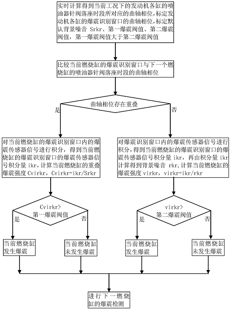
[0042] Engine knock detection methods, such as figure 1 As shown, including the following steps:

[0043] 1. Real-time calculation of the crankshaft phase corresponding to the injector needle valve seating period of each cylinder of the engine under the current working condition, calibrate the crankshaft phase of the knock recognition window of each cylinder of the engine, and calibrate the default background noise Srkr, first knock Threshold, the second knock threshold, the first knock threshold is greater than the second knock threshold;

[0044] 2. Compare the knock recognition window of the current combustion cylinder with the crankshaft phase during the seat period of the injector needle valve of the next combustion cylinder;

[0045] 3. If the injector needle valve seating period of the next combustion cylinder overlaps with the crankshaft phase of the knock recognition window of the current combustion cylinder, it is judged that there is injector seating noise entering the kno...

Embodiment 2

[0054] Based on the engine knock detection method of Embodiment 1, in step 1, the first angle and the second angle are also calibrated, and the first angle is smaller than the second angle;

[0055] In step 5, if knocking of the current combustion cylinder is detected, the ignition angle of the current combustion cylinder is delayed less than the first angle; if it is detected that the current combustion cylinder does not knock, the ignition angle of the current combustion cylinder is not delayed;

[0056] In step 7, if it is detected that the current combustion cylinder is knocking, the ignition angle of the current combustion cylinder is delayed less than the second angle; if it is detected that the current combustion cylinder does not knock, the ignition angle of the current combustion cylinder is not delayed.

[0057] In the engine knock detection method of the second embodiment, if it is detected that the current combustion cylinder is knocking, the ignition angle of the current ...

Embodiment 3

[0059] Based on the engine knock detection method of Embodiment 1, in step 1, the first time and the second time are also calibrated, and the first time is less than the second time;

[0060] In step 4, filter the knock sensor signal integrated quantity ikr of the knock recognition window of the current combustion cylinder within the first time, calculate the background noise of the current cycle of the knock recognition window of the current combustion cylinder, and complete the background noise learning;

[0061] In step 6, filter the knock sensor signal integrated quantity ikr of the knock recognition window of the current combustion cylinder in the second time, calculate the background noise of the current cycle of the knock recognition window of the current combustion cylinder, and complete the background noise learning.

[0062] In the engine knock detection method of the third embodiment, when the seat noise of the injector enters the knock recognition window of the current com...


PUM


Abstract

The invention discloses an engine detonation detection method. A crankshaft phase of a detonation identification window of a current combustion cylinder is compared with a crankshaft phase of an oil-fuel injector needle-valve seating period of a next combustion cylinder; whether oil-fuel injector seating noise enters the detonation identification window of the current combustion cylinder is determined; if so, an overlapping detonation intensity Cvirkr of the current combustion cylinder is calculated by using default background noise Srkr before the detonation identification window of the current combustion cylinder comes, wherein the Cvirkr is equal to ikr/Srkr and the ikr expresses a detonation sensor signal integration value of the detonation identification window of the current combustion cylinder; and bercause the default background noise is larger than a detonation sensor signal integration value of a detonation identification window of an internal combustion cylinder normally and a detonation detection threshold value increases, erroneous engine detonation judgement caused by entrance of the oil-fuel injector seating noise into the detonation identification window of the current combustion cylinder can be reduced. In addition, the invention also discloses a preignition detection method of an engine.

Description

Technical field [0001] The invention relates to engine control technology, in particular to an engine knock detection method and an engine pre-ignition detection method. Background technique [0002] The knock sensor is an acceleration sensor that can detect the vibration sound waves of the object. If the engine has abnormal knock combustion or pre-ignition, the vibration sound waves are detected by the knock sensor and converted into electrical signals and input into the electronic control unit. When the electronic control unit detects the occurrence of knocking combustion, the electronic control unit will adjust the ignition to avoid the occurrence of continuous knocking combustion; when the electronic control unit detects pre-ignition, the electronic control unit will cut off the fuel, enrich the mixture, Restrict the throttle and other measures to protect the engine. A knock sensor is usually installed on a 4-cylinder in-line engine, which monitors the combustion of the engi...

Claims


Application Information

Patent Timeline
IPC IPC(8): G01L23/22F02B77/08
Inventor 蔡建姚辉张力华於仕达
Owner UNITED AUTOMOTIVE ELECTRONICS SYST
Why Eureka
Try Eureka