
Monitoring system and monitoring-anomaly location method for photovoltaic power stations

A photovoltaic power station and monitoring system technology, applied in photovoltaic system monitoring, photovoltaic power generation, photovoltaic modules, etc., can solve the problems of photovoltaic power generation system efficiency reduction, photovoltaic array damage, and untimely handling of photovoltaic array faults, and improve stability. and data processing power, the effect of reducing the number of references

Active Publication Date: 2017-05-24
GUANGXI UNIV +1
View PDF5 Cites 17 Cited by
  • Summary
  • Abstract
  • Description
  • Claims
  • Application Information

AI Technical Summary

Problems solved by technology

At present, the management and maintenance of photovoltaic power plants mainly rely on manual inspection. When one of the photovoltaic arrays fails, it is difficult to find out which photovoltaic array is damaged in time.
If the failure of the photovoltaic array cannot be accurately located in time, the failure cannot be eliminated in time, and the abnormality of a single photovoltaic array will cause a significant reduction in the efficiency of the entire photovoltaic power generation system
At present, the untimely handling of photovoltaic array failures is one of the important factors that lead to the inability to maximize the power generation benefits of photovoltaic power plants.

Method used


Image

  • Monitoring system and monitoring-anomaly location method for photovoltaic power stations
  • Monitoring system and monitoring-anomaly location method for photovoltaic power stations
  • Monitoring system and monitoring-anomaly location method for photovoltaic power stations

Examples


Embodiment Construction

[0038] Embodiment of monitoring system of photovoltaic power station

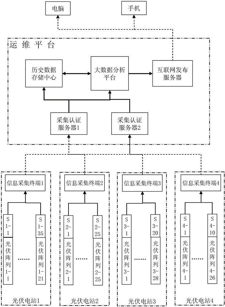
[0039] figure 1 Shown is a schematic structural diagram of an embodiment of the monitoring system of the photovoltaic power plant. In the figure, the dotted connection line represents the Internet connection, the thick solid line connection represents the Ethernet connection, and the thin solid line connection represents the CAN bus connection. A set of operation and maintenance platform and management of 4 photovoltaic power plants, N is 1,2,3,4. Photovoltaic power station 1 includes 21 photovoltaic arrays, numbered 1-1 to 1-21, wherein each photovoltaic array is composed of 36 photovoltaic modules connected in series and parallel. The photovoltaic power station 2 includes 25 photovoltaic arrays, numbered 2-1 to 2-25, and each photovoltaic array is composed of 48 photovoltaic modules connected in series and parallel. The photovoltaic power station 3 consists of 28 photovoltaic arrays, numbered 3-1 to 3-2...


PUM


Abstract

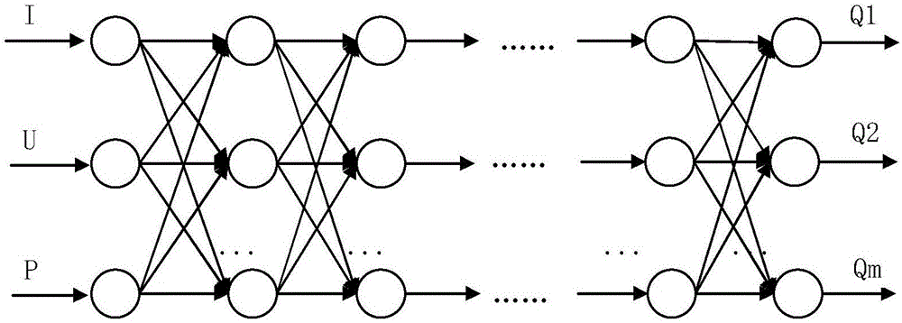
The invention relates to a monitoring system and monitoring-anomaly location method for photovoltaic power stations. According to the monitoring system, an information collection terminal of each photovoltaic power station is connected to a sensor for collecting state data of each photovoltaic array in the information collection terminal through a field bus; and each information collection terminal is connected to a collection authentication server of an operation platform through the internet, and the operation platform is in mutual connection with a historical data storage center and a big data analysis platform through the Ethernet. The method mainly comprises the following steps: (I) collecting data; (II) training a multi-hidden layer neural network by virtue of historical status data to obtain abnormal value detection method under the same illumination intensity, and carrying out abnormal value detection on current data, so as to realize the diagnosis and precise positioning of faults of the photovoltaic arrays; and (III) displaying a monitoring result and abnormal positioning information in real time, or pushing the monitoring result and the abnormal positioning information to relevant mobile phones or computers through an internet announce server. According to the monitoring system and the monitoring-anomaly location method, a deep structural model is established, so that the reference number is effectively reduced; and meanwhile, multiple photovoltaic power stations are simultaneously monitored, and the abnormity is timely found and positioned, so that the normal operation of the photovoltaic arrays is guaranteed.

Description

technical field [0001] The invention relates to the technical field of photovoltaic power generation, in particular to a monitoring system of a photovoltaic power station and a method for monitoring and abnormal location. Background technique [0002] In recent years, with the decrease of non-renewable energy sources such as petroleum and coal, the development of clean energy represented by photovoltaic power generation has become an industry direction supported by national policies. [0003] Photovoltaic power generation is a fluctuating and intermittent power source. Compared with traditional power generation, it is an uncontrollable power source. For example, the increasingly severe smog weather will inevitably affect the efficiency of photovoltaic power generation. In order to reduce the impact of photovoltaic power generation from such random environmental changes and improve power generation efficiency, it is necessary to strengthen the intelligent monitoring of the op...

Claims


Application Information

Patent Timeline
IPC IPC(8): H02S50/00
CPCH02S50/00Y02E10/50
Inventor 叶进段家慧王钰淞谢敏何华光胡亮青
Owner GUANGXI UNIV
Learn More