Method and apparatus for sending demodulation reference signal, base station and terminal

A demodulation reference signal and terminal technology, which is applied in the field of sending demodulation reference signals, can solve the problems of power imbalance between OFDM symbols and the inability to meet the matching requirements, and achieve the effect of maintaining power balance and ensuring backward compatibility

Active Publication Date: 2017-05-24
CHINA MOBILE COMM GRP CO LTD
View PDF7 Cites 11 Cited by
  • Summary
  • Abstract
  • Description
  • Claims
  • Application Information

AI Technical Summary

Problems solved by technology

However, the MU-MIMO defined in the existing standard only supports a maximum of 4 streams, and the DMRS design with a maximum of 2 streams per user cannot meet the needs of more user pairing under 3DMIMO
[0030] When a maximum of 8 streams are transmitted by multiple users, in the DMRS configuration realized by using 12RE, OCC=4 and 2 scrambling codes, if the OCC bitmap method defined by the existing standard is directly used, there will be power imbalance between OFDM symbols question

Method used


Image

  • Method and apparatus for sending demodulation reference signal, base station and terminal
  • Method and apparatus for sending demodulation reference signal, base station and terminal
  • Method and apparatus for sending demodulation reference signal, base station and terminal

Examples


no. 1 example

[0090] Such as Figure 8 As shown, the first embodiment of the present invention provides a method for sending a demodulation reference signal, which is applied to a base station, and the method includes:

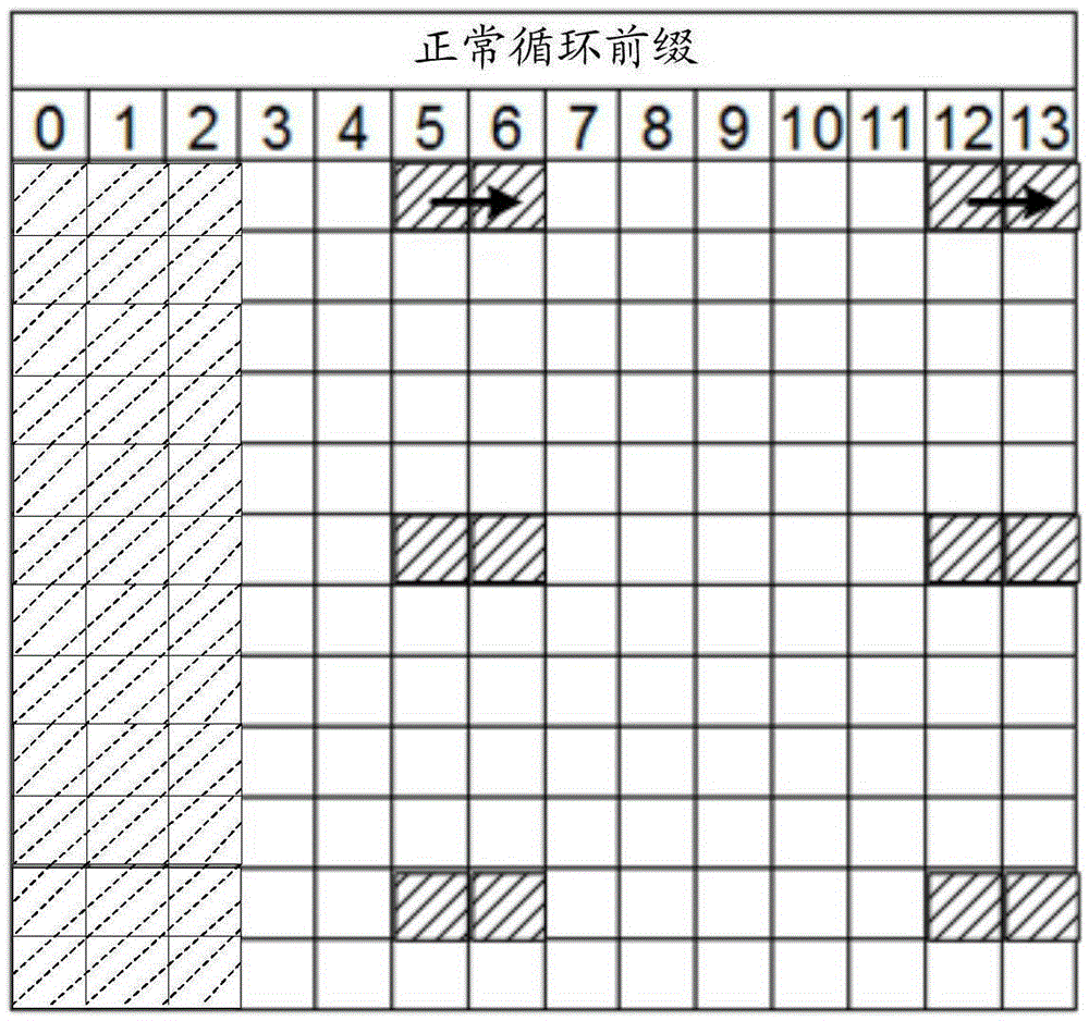
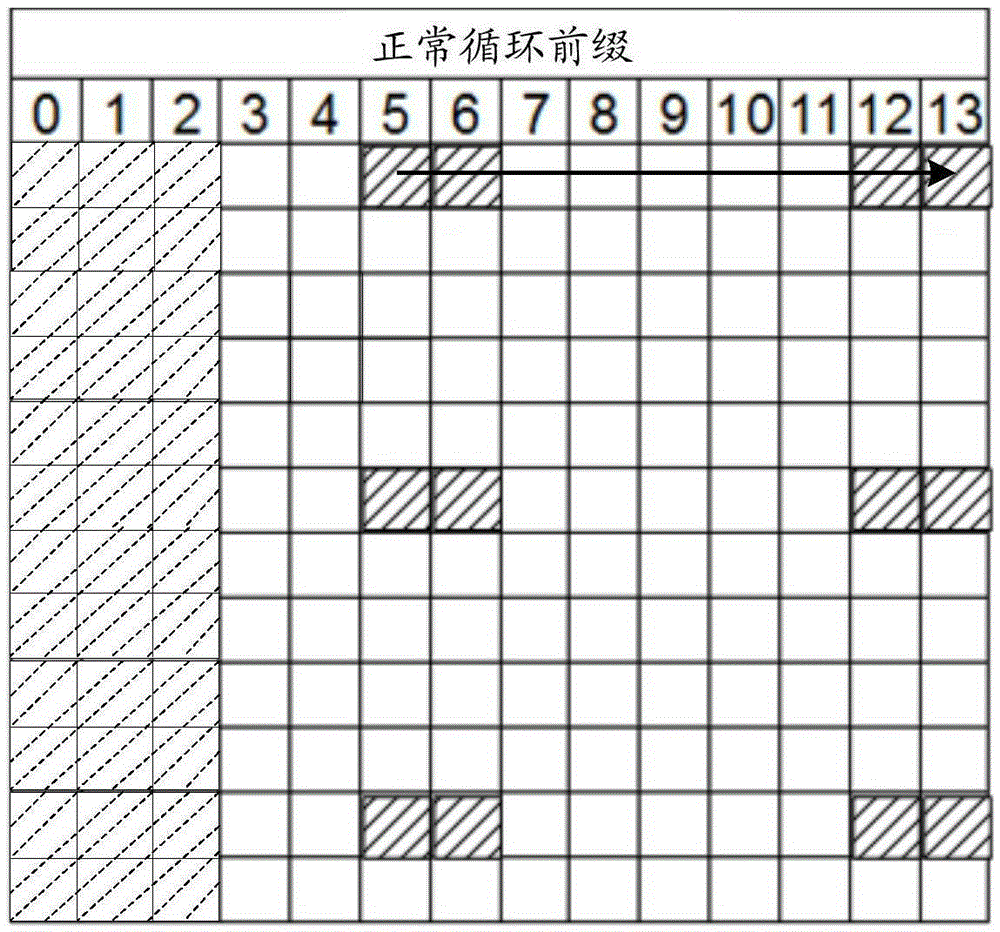
[0091] In step S801, the DMRS sent to the terminal through the demodulation reference signal port 7 and the DMRS port 8 is mapped using a first mapping order to obtain a first DMRS.

[0092] In the first embodiment of the present invention, the orthogonal mask sequence for mapping the DMRS sent to the terminal through the demodulation reference signal (DMRS) port 7 and DMRS port 8 is the same as that of the existing standard .

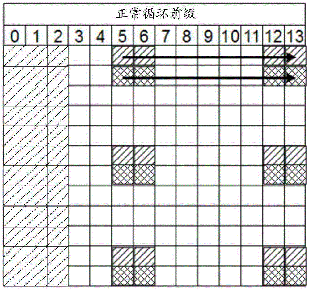
[0093] Step S802, performing mapping processing on the DMRS sent to the terminal through the DMRS port 11 and the DMRS port 13 using the second mapping order to obtain a second DMRS.

[0094] Wherein, the above-mentioned first mapping order is opposite to the second mapping order.

[0095] In the first embodiment of the present invention, the abo...

no. 2 example

[0122] Such as Figure 12 As shown, the second embodiment of the present invention provides a device for sending a demodulation reference signal, which is applied to a base station, and the device includes:

[0123] The first mapping module 1201 is configured to perform mapping processing on the DMRS sent to the terminal through the demodulation reference signal DMRS port 7 and DMRS port 8 using a first mapping order to obtain a first DMRS;

[0124] The second mapping module 1202 is configured to perform mapping processing on the DMRS sent to the terminal through the DMRS port 11 and the DMRS port 13 using a second mapping order to obtain a second DMRS; wherein, the first mapping order is opposite to the second mapping order;

[0125] The sending module 1203 is configured to send the first DMRS and / or the second DMRS to the terminal.

[0126] Among them, the device also includes:

[0127] The first acquiring module is configured to acquire a first orthogonal mask sequence fo...

no. 3 example

[0141] A third embodiment of the present invention provides a base station, including the above-mentioned device for sending a demodulation reference signal.

[0142] It should be noted that the base station provided by the third embodiment of the present invention is a base station including the above-mentioned device for sending a demodulation reference signal applied to a base station, that is, all embodiments of the above-mentioned device for sending a demodulation reference signal applied to a base station are applicable based on the base station, and can achieve the same or similar beneficial effects.


PUM


Abstract

The embodiment of the invention provides a method and apparatus for sending a demodulation reference signal, a base station and a terminal. The method comprises the following steps: mapping DMRS sent by a demodulation reference signal DMRS port 7 and a DMRS port 8 to the terminal in a first mapping sequence to obtain a first DMRS; mapping the DMRS sent by a DMRS port 11 and a DMRS port 13 to the terminal in a second mapping sequence to obtain a second DMRS, wherein the first mapping sequence and the second mapping sequence are opposite; and sending the first DMRS and / or the second DMRS to the terminal. By adoption of the method provided by the embodiment of the invention, in the case of multiuser maximum 8-flow transmission, the power of an orthogonal frequency division multiplexing symbol is balanced while backward compatibility is guaranteed.

Description

technical field [0001] The present invention relates to the field of wireless technology, in particular to a method, device, base station and terminal for sending a demodulation reference signal. Background technique [0002] Existing communication systems, such as Long Term Evolution (LTE, Long Term Evolution), Worldwide Interoperability for Microwave Access (WiMax, Worldwide Interoperability for Microwave Access), and 802.11n, all adopt the traditional 2D Multiple Input Multiple Output (MIMO, Multiple -IZPut Multiple-Output,) technology, its basic principle is to improve the transmission quality and system capacity through the two-dimensional spatial freedom on the horizontal plane. With the development of antenna design architecture, in order to improve the transmission efficiency of mobile communication systems and improve user experience, it is necessary to fully exploit the degree of freedom in vertical space, extend the traditional 2D MIMO technology to 3D MIMO techno...

Claims


Application Information

Patent Timeline
Patent Type & Authority Applications(China)
IPC IPC(8): H04L5/00
CPCH04L5/001H04L5/0048H04L5/0053
Inventor 金婧吴丹童辉沈晓冬
Owner CHINA MOBILE COMM GRP CO LTD
Why Eureka
Try Eureka