

Oil-water separation heat-dissipation system
A heat dissipation system, oil-water separation technology, applied in the direction of immiscible liquid separation, cooking utensils, household utensils, etc., can solve problems such as inability to separate, and achieve the effect of avoiding waste
- Summary
- Abstract
- Description
- Claims
- Application Information
AI Technical Summary
Problems solved by technology
Method used
Image

Examples
Embodiment Construction
[0014] In order to make the technical means, creative features, goals and effects achieved by the present invention easy to understand, the present invention will be further described below in conjunction with specific embodiments.
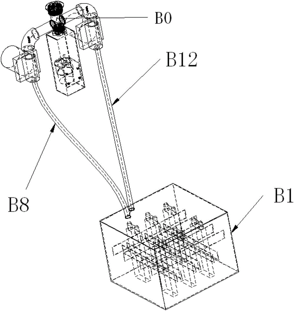
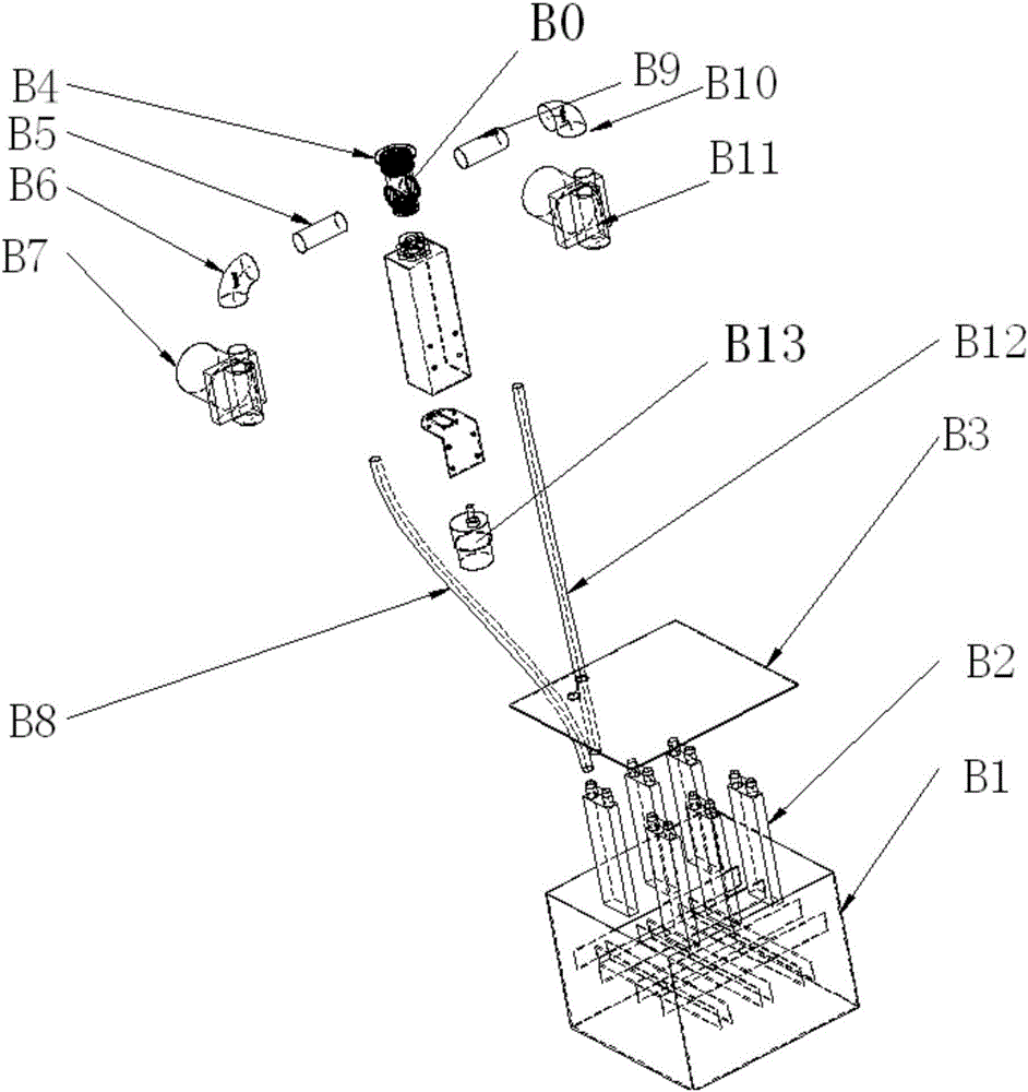
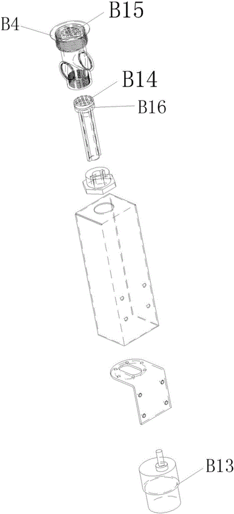
[0015] Embodiments of the present invention provide an oil-water separation cooling system, see figure 1 As shown, it includes: a shunt switch device arranged at the filter port at the bottom of the wok and a cooling device connected to the shunt switch device, the shunt switch device is used for shunting and discharging oil and water, and the cooling device cools the oil And collect the cooled oil. see figure 2 , the shunt switch device includes: a shunt switch housing B0 whose top communicates with the filter port, the shunt switch housing is a cylindrical hollow structure, and the inside of the shunt switch housing is provided with a switch head B16 for dredging through the filter port and preventing the filter port from clogging, The switch...
PUM
 Abstract
Description
Claims
Application Information