
Degassing filter

A filter and filter cartridge technology, which is applied in the direction of fixed filter element filter, filter separation, filter circuit, etc., can solve the problem of incomplete exhaust of the getter filter, so as to facilitate daily maintenance, facilitate instrument maintenance, and prolong the use The effect of longevity

Inactive Publication Date: 2017-05-31
郑州盈嘉石油工程技术有限公司
View PDF7 Cites 1 Cited by
  • Summary
  • Abstract
  • Description
  • Claims
  • Application Information

AI Technical Summary

Problems solved by technology

[0005] The object of the present invention is to: aim at the problem of incomplete exhaust of the above-mentioned existing air getter filter, the present invention provides a kind of air getter filter

Method used


Image

  • Degassing filter
  • Degassing filter
  • Degassing filter

Examples


Embodiment 1

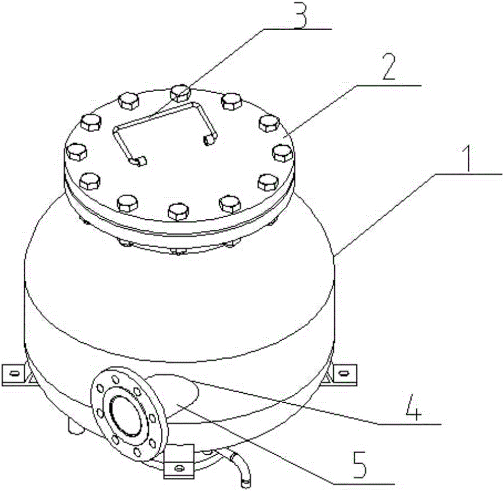
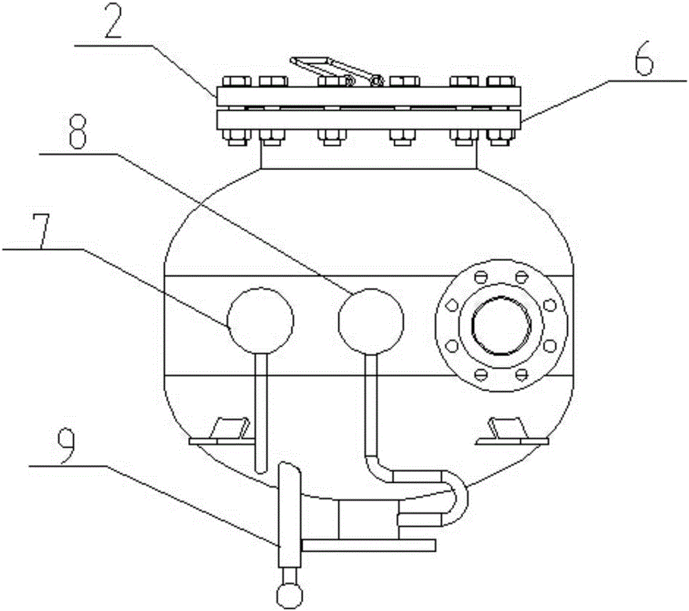
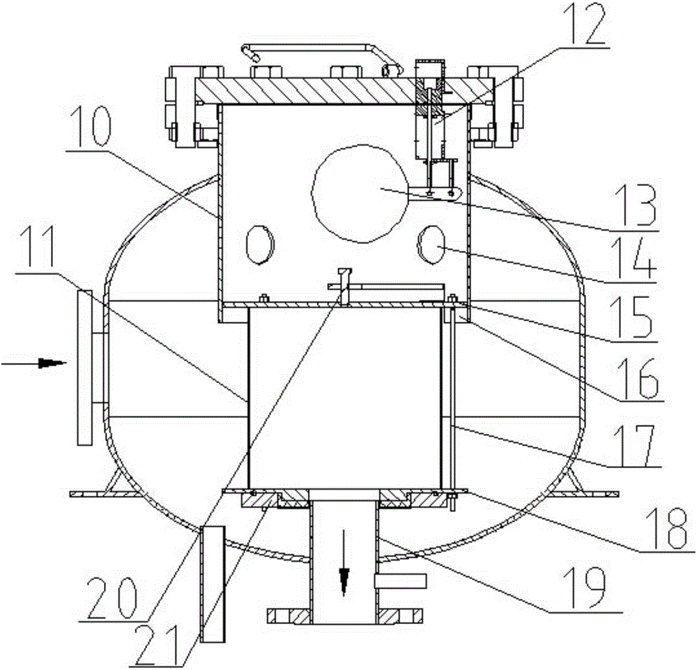
[0031] A degassing filter, comprising a cylinder 1 and an inlet 4 arranged on one side of the cylinder 1, a filter cartridge 11 is arranged inside the cylinder 1, and the top of the filter cartridge 11 is fixedly connected to an exhaust device and communicated with the exhaust device, The inlet 4 is arranged tangentially along the side wall of the cylinder body 1; the top of the cylinder body 1 is provided with an opening that cooperates with the exhaust device, and the exhaust device includes an inner cylinder 10, and the top of the inner cylinder 10 passes through the opening and Extending to the outside of the cylinder body 1, the top of the inner cylinder 10 is provided with a sealing device, the sealing device is provided with an exhaust port and an exhaust valve 12 installed at the exhaust port, and the inner cylinder 10 is also provided with an exhaust valve. The floating ball 13 matched with the air valve 12; diversion openings 14 are evenly distributed on the side wall...

Embodiment 2

[0034] Based on Embodiment 1, an inlet pipe 5 is provided at the inlet 4, and the inlet pipe 5 is used to connect the oil pipeline. The inlet pipe 5 is inclined downward at an angle of 17°, so that when the oil enters the barrel 1 at high speed, a swirl flow 22 is formed upward along the inner wall, which is beneficial for the oil to enter the inner barrel 10 from the diversion port 14 .

Embodiment 3

[0036]Based on Embodiment 1, the sealing device is a top cover 2 , and a third flange 6 is connected to the top of the inner cylinder 10 , and the top cover 2 and the inner cylinder 10 are bolted through the third flange 6 . The top of the inner cylinder 10 can be sealed through the top cover 2 and the third flange 6 to ensure gas accumulation on the upper part of the inner cylinder 10, and the bolt connection is a detachable fixed connection, which has the advantages of simple structure, reliable connection, and convenient disassembly. It is convenient to overhaul and clean the exhaust device.


PUM


Abstract

A degassing filter comprises a barrel and an inlet formed on one side of the barrel, wherein the barrel is internally provided with a filter cylinder; the top of the filter cylinder is fixedly connected and communicated with an exhaust device; the inlet is formed in a tangential direction of a side wall of the barrel; an opening matched with the exhaust device is formed at the top of the barrel; the exhaust device comprises an inner cylinder; the top of the inner cylinder penetrates through the opening and extends to the outside of the barrel; a sealing device is arranged at the top of the inner cylinder; an exhaust port and an vent valve mounted at the exhaust port are formed and arranged on the sealing device; the inner cylinder is further internally provided with a floating ball matched with the exhaust valve; guide ports are uniformly distributed in a side wall of the inner cylinder; a horizontal plane where the guide ports are located is lower than a horizontal plane where the floating ball is located; an outlet is formed at the bottom of the barrel; an outlet pipe is arranged at the outlet; one end of the outlet pipe is communicated with the bottom of the filter cylinder; and the other end of the outlet pipe penetrates through the outlet and extends to the outside of the barrel. According to the filter, gas is separated from oil by a centrifugal force; the gas can be helped to timely escape from the oil; a thorough exhaust effect is achieved; and similarly, the filter is applicable to a situation of higher oil flow velocity.

Description

technical field [0001] The invention relates to a filter device for pipeline fluid, in particular to an air-eliminating filter. Background technique [0002] The degassing filter is one of the auxiliary equipment of the flowmeter, which can separate the solid impurities and gases in the pipeline fluid, prevent the solid impurities and gases in the fluid from affecting the measurement accuracy of the flowmeter, and prolong the service life of the flowmeter. [0003] After the fluid enters the degassing filter, it passes through the internal filter to remove solid impurities. When the liquid passes through the filter assembly, it will change the flow direction, so that the free gas and part of the dissolved gas in the oil can fully escape and gather in the On the top of the getter filter, a gas space is formed, and an oil-gas interface appears. As the gas increases and the pressure increases, the oil-gas interface descends, and the floating ball descends with the oil-gas inte...

Claims


Application Information

Patent Timeline
Patent Type & Authority Applications(China)
IPC IPC(8): B01D35/02B01D29/33B01D29/90B01D35/01
CPCB01D36/001
Inventor 彭志刚王晓光张松领
Owner 郑州盈嘉石油工程技术有限公司
Learn More