Supercharge Your Innovation With Domain-Expert AI Agents!

Fence pile continuous rolling unit

A continuous rolling and fence technology, applied in metal rolling, metal rolling and other directions, can solve problems such as large consumption of raw materials, large investment in manpower, hidden dangers of steel safety, etc., to reduce unsafe factors, improve product quality, and achieve a high degree of automation. Effect

Active Publication Date: 2017-05-31
唐山市丰南区嘉谊牧栏杆厂
View PDF7 Cites 0 Cited by
  • Summary
  • Abstract
  • Description
  • Claims
  • Application Information

AI Technical Summary

Problems solved by technology

[0004] 1. A lot of manpower is invested, and the labor cost is high. 19 people need to be invested in the whole rolling process
[0005] 2. During the steel rolling process, after the steel billet passes through the rolling hole of the rolling mill, there is no roller table behind the rolling mill, forming irregular movement, and the temperature is high. There is a great safety hazard in the manual operation of transferring steel, and accidents are prone to occur
[0006] 3. The steel rolling time is long and the temperature difference is large
[0007] 4. The consumption of raw materials is large. Due to the short length of the manually operated billets, the length of each billet cannot exceed 1 meter, resulting in many scrap heads
[0008] 5. The production efficiency of manual operation is low, and the annual output is about 15,000 tons
[0009] 6. Manual operation is labor-intensive
[0010] The continuous rolling mills currently producing fences have low production efficiency and low output

Method used


Image

  • Fence pile continuous rolling unit
  • Fence pile continuous rolling unit
  • Fence pile continuous rolling unit

Examples


Embodiment Construction

[0041] The present invention will be further described below in conjunction with the accompanying drawings and embodiments.

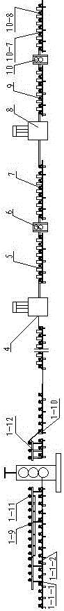
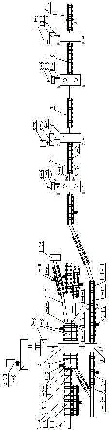
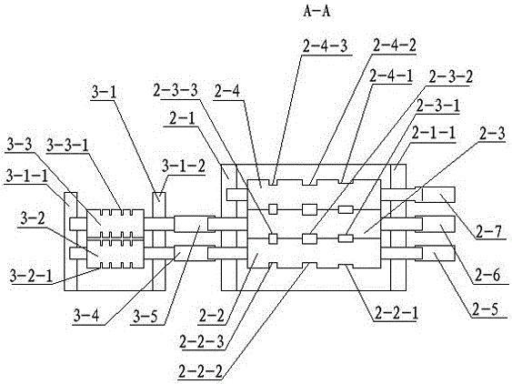
[0042] see Figure 1 to Figure 14 , The fence pile continuous rolling unit described in this embodiment includes a roughing mill, the roughing mill is a reciprocating rolling mill, and the roughing mill includes a first roughing mill 2 and a second roughing mill 3 arranged side by side. The first rough rolling mill 2 comprises the first rough rolling mill left support 2-1, the first rough rolling right support 2-1-1, and the first rough rolling roll 2-2, the second rough rolling roll 2-2 are successively arranged in the support from bottom to top 3. The third rough roll 2-4, the first rough roll 2-2, the second rough roll 2-3, and the third rough roll 2-4 are respectively provided with bearing housings. The side where the rough roll is connected to the motor is the driving side, and the side corresponding to the driving side is the working side. The d...


PUM


Abstract

The invention relates to metallurgical steel rolling equipment, in particular to a fence pile continuous rolling unit. The fence pile continuous rolling unit comprises a rough-rolling roller way, a rough-rolling mill, a finish-rolling mill, a finish-rolling mill roller way. The finish-rolling mill comprises a first finish-rolling mill, a second finish-rolling mill, a third finish-rolling mill and a fourth finish-rolling mill. The first and third finish-rolling mills are vertical rolling mills. The first, second, third and fourth finish-rolling mills are connected in sequence through the finish-rolling roller way. A first finish-rolling roller and a second finish-rolling roller of the first finish-rolling mill are provided with an annular first finish-rolling groove and an annular second finish-rolling groove correspondingly. A third finish-rolling roller of the second finish-rolling mill is provided with an annular third finish-rolling groove. An intermittent fourth finish-rolling groove is formed in the periphery of a fourth finish-rolling roller of the second finish-rolling mill. A fifth finish-rolling roller and a sixth finish-rolling roller of the third finish-rolling mill are provided with an annular fifth finish-rolling groove and an annular sixth finish-rolling groove correspondingly. A seventh finish-rolling roller and an eighth finish-rolling roller of the fourth finish-rolling mill are provided with an annular seven finish-rolling groove and an annular eighth finish-rolling groove correspondingly. The production efficiency is high, the yield is high, and the product quality is improved.

Description

technical field [0001] The invention relates to metallurgical steel rolling equipment, in particular to a fence pile continuous rolling unit. Background technique [0002] The original rolling mill equipment is a horizontal three-and-a-half 250 rolling mill, and the steel billet is rolled into a finished fence pile by two passes. During the rolling process of the steel billet, the steel is sequentially transferred to two rolling processes through the manual operation of the longitudinal rolling mill unit, and rolled into finished products. [0003] The above-mentioned rolling method is manually operated, but there are following problems in the rolling process: [0004] 1. A lot of manpower is invested, and the labor cost is high. 19 people need to be invested in the whole rolling process. [0005] 2. During the steel rolling process, after the steel billet passes through the rolling hole of the rolling mill, there is no roller table behind the rolling mill, forming irregul...

Claims


Application Information

Patent Timeline
Patent Type & Authority Applications(China)
IPC IPC(8): B21B1/12B21H8/02
CPCB21B1/12B21H8/02
Inventor 孙仕忠
Owner 唐山市丰南区嘉谊牧栏杆厂
Features
  • R&D
  • Intellectual Property
  • Life Sciences
  • Materials
  • Tech Scout
  • Unparalleled Data Quality
  • Higher Quality Content
  • 60% Fewer Hallucinations
Learn More