Automatic-following pressure balance ring-shaped drive device and application method thereof

A technology of driving device and balancing pressure, which is applied in the field of ring driving device that automatically follows the balanced pressure, can solve the problems that small-diameter plunger cylinders cannot meet the requirements of high precision and synchronicity, and that large-diameter driving devices can be placed. Compact, easy-to-control effects

Active Publication Date: 2017-05-31
CHINA NAT HEAVY MACHINERY RES INSTCO
View PDF5 Cites 1 Cited by
  • Summary
  • Abstract
  • Description
  • Claims
  • Application Information

AI Technical Summary

Problems solved by technology

[0003] The purpose of the present invention is to overcome the problem that the compound molding machine cannot place a large-diameter driving device in the center of the frame, and the placement of several small-diameter plunger cylinders cannot meet the requirements of high precision and synchronization

Method used


Image

  • Automatic-following pressure balance ring-shaped drive device and application method thereof
  • Automatic-following pressure balance ring-shaped drive device and application method thereof
  • Automatic-following pressure balance ring-shaped drive device and application method thereof

Examples


Embodiment 1

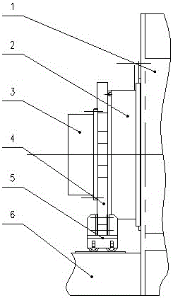
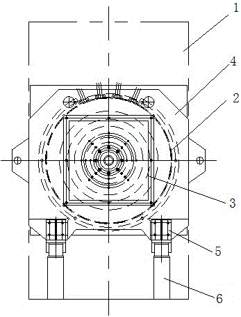
[0020] In order to overcome the problem that the compound molding machine cannot place a large-diameter driving device in the center of the frame, and several small-diameter plunger cylinders cannot meet the requirements of high precision and synchronization, this embodiment provides the following figure 1 and figure 2 A circular driving device that automatically follows the balanced pressure shown includes a frame 1, and a circular driving device 2 is installed on the frame 1 through a hydraulic nut 12. The circular driving device 2 is connected to the water inlet valve body 3 through a connecting device 4, connected to The support device 5 is connected to the bottom of the device 4, and the support device 5 is slidably connected with the track 6 located below; The device 2 is also connected to the industrial computer.

[0021] The principle of the ring drive device that automatically follows the balanced pressure is as follows: the ring drive device 2 pushes the connection...

Embodiment 2

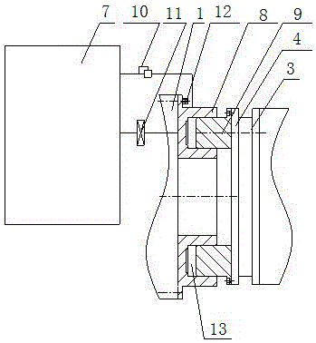
[0025] On the basis of Example 1, such as image 3 As shown, the annular driving device 2 includes an oil tank 7, an annular cylinder 8, an annular push rod 9 and an automatic adjustment circuit 10, the annular cylinder 8 is installed on the frame 1 through a hydraulic nut 12, and the annular push rod 9 is inserted into the annular In the cylinder body 8, a chamber 13 is formed between the annular push rod 9 and the annular cylinder body 8, and the chamber 13 and the oil tank 7 are communicated through an automatic adjustment circuit 10, and a shut-off valve 11 is installed on the automatic adjustment circuit 10; The connecting device 4 is fixedly mounted on the annular push rod 9 .

[0026] The working principle of ring drive device 2 is:

[0027] When the pressure of the water inlet valve body 3 changes, the annular push rod 9 is under the action of the automatic adjustment circuit 10. If the axial force provided by the water inlet valve body 3 is less than the axial force ...

Embodiment 3

[0029] On the basis of Embodiment 1, it should be noted that the connecting device 4 is a weldment composed of two flanges, one of which is connected to the annular push rod 9 through bolts, and the other flange is connected to the push rod 9 through bolts. The water valve body 3 is connected.


PUM


Abstract

The invention provides an automatic-following pressure balance ring-shaped drive device and an application method thereof. The automatic-following pressure balance ring-shaped drive device comprises a rack, wherein a ring-shaped drive device is mounted on the rack through a hydraulic nut; the ring-shaped drive device is connected with a water inlet valve body through a connecting device; a supporting device is connected below the connecting device; the supporting device is in sliding connection with a rail below the supporting device; and the ring-shaped drive device is further connected with an industrial controller. The automatic-following pressure balance ring-shaped drive device makes up the control precision defects and the structural defects caused by simultaneous movement of a plurality of cylinders in the past, and has the advantages of being simple in structure, high in working efficiency, easy to realize automatic control and the like. Especially, the automatic-following balance pressure ring-shaped drive device adopts an independent ring-shaped drive device; only one drive device is provided, so that control is simple, and synchronous following pressure balance performances are good, and therefore, the problem that the conventional structure cannot be used for placing large-diameter cylinders, and a plurality of small cylinders cannot meet high-precision synchronization requirements is solved.

Description

technical field [0001] The invention belongs to the field of hydraulic forming of pipe equipment, and in particular relates to an annular drive device that automatically follows the balance pressure. Background technique [0002] The balance axial force device of traditional composite pipe equipment and hydraulic forming equipment generally adopts a large-diameter plunger cylinder or multiple small-diameter plunger cylinders to bear the axial force generated by the pipe during the test process. There are other equipment positions in the center of the rack, so a large-diameter plunger cylinder cannot be directly prevented. Since multiple plunger cylinders have high requirements for synchronization during the forward process, if several cylinders with smaller diameters are evenly distributed around the center The plug cylinder is difficult to control the precision of the forward displacement, and cannot meet the requirements of high precision and synchronization. Contents of...

Claims


Application Information

Patent Timeline
Patent Type & Authority Applications(China)
IPC IPC(8): B21D26/043
CPCB21D26/043
Inventor 刘邯涛赵西韩朱纪刚杨鹏
Owner CHINA NAT HEAVY MACHINERY RES INSTCO
Why Eureka
Try Eureka