An application method of an automatic follow-up balance pressure ring drive device
A technology of driving device and balancing pressure, which is applied in the field of ring driving device that automatically follows balanced pressure, can solve the problems that small-diameter plunger cylinders cannot meet high-precision requirements and synchronization requirements, and that large-diameter driving devices can be placed. Compact, easy-to-control effects
- Summary
- Abstract
- Description
- Claims
- Application Information
AI Technical Summary
Problems solved by technology
Method used
Image
Examples
Embodiment 1
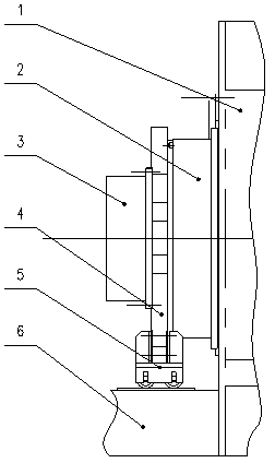
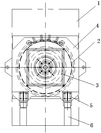
[0020] In order to overcome the problem that the compound molding machine cannot place a large-diameter driving device in the center of the frame, and several small-diameter plunger cylinders cannot meet the requirements of high precision and synchronization, this embodiment provides the following figure 1 and figure 2 A circular driving device that automatically follows the balanced pressure shown includes a frame 1, and a circular driving device 2 is installed on the frame 1 through a hydraulic nut 12. The circular driving device 2 is connected to the water inlet valve body 3 through a connecting device 4, connected to The support device 5 is connected to the bottom of the device 4, and the support device 5 is slidably connected with the track 6 located below; The device 2 is also connected to the industrial computer.
[0021] The principle of the ring-shaped driving device that automatically follows the balanced pressure is as follows: the ring-shaped driving device 2 pus...
Embodiment 2
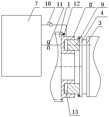
[0025] On the basis of Example 1, such as image 3 As shown, the annular driving device 2 includes an oil tank 7, an annular cylinder 8, an annular push rod 9 and an automatic adjustment circuit 10, the annular cylinder 8 is installed on the frame 1 through a hydraulic nut 12, and the annular push rod 9 is inserted into the annular In the cylinder body 8, a chamber 13 is formed between the annular push rod 9 and the annular cylinder body 8, and the chamber 13 and the oil tank 7 are communicated through an automatic adjustment circuit 10, and a shut-off valve 11 is installed on the automatic adjustment circuit 10; The connecting device 4 is fixedly mounted on the annular push rod 9 .
[0026] The working principle of ring drive device 2 is:
[0027] When the pressure of the water inlet valve body 3 changes, the annular push rod 9 is under the action of the automatic adjustment circuit 10. If the axial force provided by the water inlet valve body 3 is less than the axial force ...
Embodiment 3
[0029] On the basis of Embodiment 1, it should be noted that the connecting device 4 is a weldment composed of two flanges, one of which is connected to the annular push rod 9 through bolts, and the other flange is connected to the push rod 9 through bolts. The water valve body 3 is connected.
PUM
 Abstract
Description
Claims
Application Information
 - R&D
- Intellectual Property
- Life Sciences
- Materials
- Tech Scout
- Unparalleled Data Quality
- Higher Quality Content
- 60% Fewer Hallucinations
Browse by: Latest US Patents, China's latest patents, Technical Efficacy Thesaurus, Application Domain, Technology Topic, Popular Technical Reports.
© 2025 PatSnap. All rights reserved.Legal|Privacy policy|Modern Slavery Act Transparency Statement|Sitemap|About US| Contact US: help@patsnap.com


