Tube piercing device

A punching and pipe technology, applied in the direction of feeding device, storage device, positioning device, etc., can solve the problems of punching waste and low punching efficiency, increase processing efficiency, improve processing efficiency, and save punching time Effect

Active Publication Date: 2017-05-31
重庆鼎汉巅宏汽车零部件有限公司
View PDF8 Cites 8 Cited by
  • Summary
  • Abstract
  • Description
  • Claims
  • Application Information

AI Technical Summary

Problems solved by technology

[0003] The object of the present invention is to provide a device for punching pipes to solve the problem of low punching efficiency due to punching waste left in the mandrel when the diameters of the pipes to be punched are different

Method used


Image

  • Tube piercing device
  • Tube piercing device

Examples


Embodiment Construction

[0014] The present invention will be described in further detail below by means of specific embodiments:

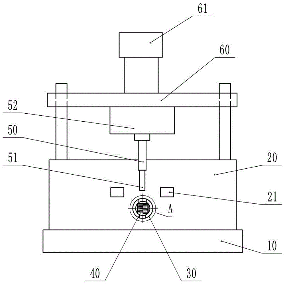
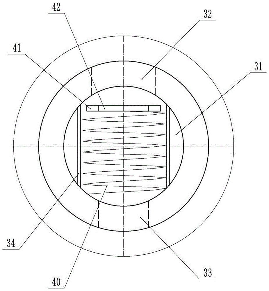
[0015] The reference signs in the drawings of the description include: base 10, fixed plate 20, limit block 21, mandrel 30, hollow cavity 31, large through hole 32, small through hole 33, pole 34, spring 40, bullet block 41, Straight hole 42, large punch 50, small punch 51, punch seat 51, pressing plate 60, die handle 61.

[0016] Such as figure 1 As shown, the device for pipe punching includes a base 10, a fixed plate 20, a mandrel 30, a punch, and a pressing plate 60. The fixed plate 20 is vertically welded on the base 10, and the mandrel 30 is welded on the fixed plate 20. The core The rod 30 is parallel to the upper surface of the base 10 and is perpendicular to the fixed plate 20; the fixed plate 20 is fixed with two stoppers 21 by bolts, and the two stoppers 21 are respectively located at the upper left and upper right of the mandrel 30. The three limit blocks 21 ...


PUM


Abstract

The invention discloses a tube piercing device. The tube piercing device comprises a base, a fixed plate, a mandrel, a punch and a pressure plate, wherein the fixed plate is perpendicularly fixed on the base; the mandrel is fixed on the fixed plate; limiting blocks are arranged on the fixed plate; guide pillars are also arranged on the fixed plate; the pressure plate penetrates through the guide pillars and is slidably connected with the guide pillars; a die shank is fixed at the upper end of the pressure plate; a punch seat is arranged at the lower end of the pressure plate; the punch comprises a small punch and a large punch; a hollow cavity is formed in the mandrel; a through hole is formed in a position, which corresponds to the punch, of the mandrel and comprises a large through hole and a small through hole; an elastic piece is arranged in the hollow cavity and positioned at the through hole; the elastic piece is fixed on the mandrel and positioned on one side close to the small through hole; and a straight hole capable of allowing the small punch to penetrate through is formed in the elastic piece. Compared with the prior art, the tube piercing device has the characteristics that holes with different sizes and diameters can be formed in a tube by punching at a time, meanwhile, wastes generated by piercing can further be discharged out of the tube and the mandrel, and therefore, the tube piercing efficiency is greatly improved.

Description

technical field [0001] The invention belongs to the technical field of punching equipment, and specifically discloses a device for punching pipes. Background technique [0002] Various types of pipes are used in the manufacture of automobiles, and some pipes need to be processed with through holes on the pipe surface, that is, two symmetrical holes need to be processed on the pipe surface of the pipe; in the existing industrial production and manufacturing, usually use Pipe punching die with mandrel. When the diameters that need to be punched are the same, put the pipe on the mandrel, and after the positioning is completed, use the punch to punch to complete the punching operation. When encountering different diameters that need to be punched, in order to save time, two large and small punches are generally used to punch the pipe at the same time; although this operation saves process steps and time, it will cause The problem that the generated waste remains inside the man...

Claims


Application Information

Patent Timeline
Patent Type & Authority Applications(China)
IPC IPC(8): B21D28/28B21D28/34B21D43/00
CPCB21D28/28B21D28/34B21D43/003
Inventor 刘文
Owner 重庆鼎汉巅宏汽车零部件有限公司
Why Eureka
Try Eureka