
Clamping cutting device

A cutting device, No. 1 technology, applied in the direction of shearing devices, shearing machine accessories, shearing machine equipment, etc., can solve the problems of bullet injuries to staff, hidden safety hazards, high maintenance costs, etc., to achieve low maintenance costs and improve Work efficiency, simple operation effect

Active Publication Date: 2017-05-31
NANTONG KAIDI AUTOMATIC MACHINERY
View PDF8 Cites 6 Cited by
  • Summary
  • Abstract
  • Description
  • Claims
  • Application Information

AI Technical Summary

Problems solved by technology

[0002] With the development of society and the improvement of people's living standards, the quality requirements for various types of panels are relatively high when building and decorating houses. When cutting some semi-finished panels, if the fixation is not good, the panels will bounce and the staff will be injured. Potential safety hazards, most of the existing fixtures are manually cut, single-function, chaotic on site after cutting, high maintenance costs, not suitable for some small and medium-sized enterprises, in order to meet market demand, better and more complete is required when manufacturing panels The equipment, in order to solve this kind of problem needs a kind of self-propelled clamping and fixing device

Method used


Image

  • Clamping cutting device
  • Clamping cutting device
  • Clamping cutting device

Examples


Embodiment Construction

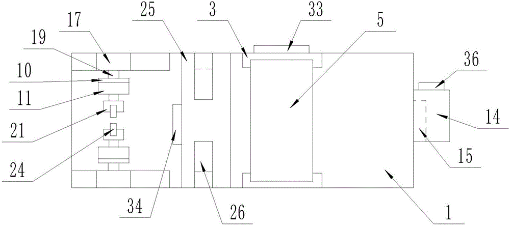
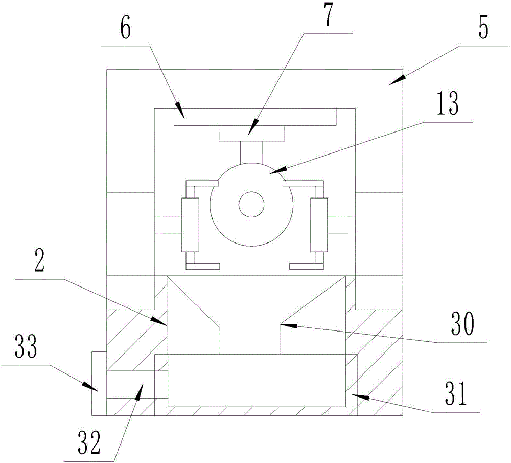
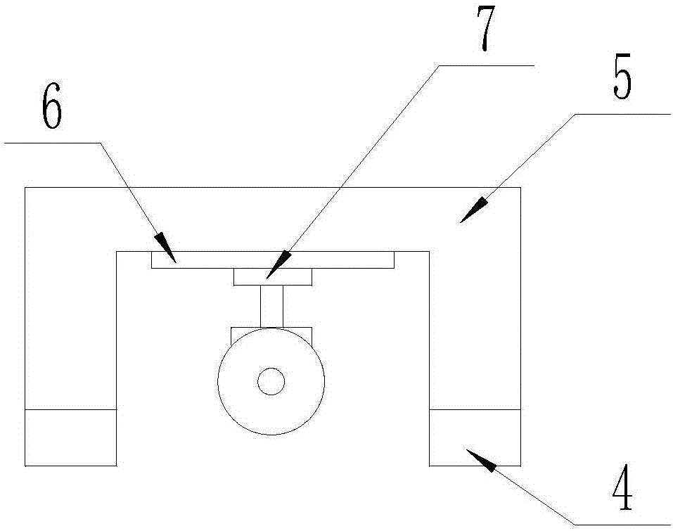
[0021] The present invention will be described in detail below with reference to the drawings, such as Figure 1-8 As shown, a clamping and cutting device includes a working table (1), the inside of the working table (1) is a cavity structure, and a rectangular opening (2) is processed at the center of the upper surface of the working table (1) A set of No. 1 slide rails (3) are provided on the upper surface of the workbench (1) and located on both sides of the No. 1 rectangular opening (2), and each No. 1 slide rail (3) is provided with a No. 1 electric trolley (4), the upper surface of each No. 1 electric trolley (4) is jointly connected with a portal frame (5), and the lower surface of the portal frame (5) is provided with a No. 2 slide rail (6) No. 2 electric trolley (7) is provided on the No. 2 slide rail (6), and a No. 1 circular groove (8) is machined on the lower surface of the No. 2 electric trolley (7). The slot (8) is provided with a No. 1 linear motor (9) with the ...


PUM


Abstract

The invention discloses a clamping cutting device comprising a working table. The interior of the working table is of a cavity structure. A first rectangular through opening is machined in the center of the upper surface of the working table. A set of first sliding rails are arranged in the position, located on the two sides of the first rectangular through opening, on the upper surface of the working table. A pushing plate matched with a first round groove is arranged at the telescopic end of a first linear motor. A controller is arranged on the surface of one side of the working table. A PLC programming system is arranged in the controller. An electronic display screen is arranged on the front surface of the controller. The output end of the PLC programming system is electrically connected with the electronic display screen. A city power connector is arranged on the lower portion of the controller. The city power connector is electrically connected with the controller. The input end of the controller is electrically connected with first electric trolleys, the PLC programming system, a second electric trolley, the first linear motor and a first rotating motor. The clamping cutting device has the beneficial effects of being simple in structure and high in practicability.

Description

Technical field [0001] The invention relates to the field of plate clamping and cutting, in particular to a clamping and cutting device. Background technique [0002] With the development of society and the improvement of people’s living standards, the quality requirements of various types of panels are relatively high during the construction and decoration of houses. When cutting some semi-finished panels, if the fixing is not good, the panels will splash and the staff will be injured. Safety hazards, most of the existing fixing devices are manual cutting, with single function, the site is chaotic after cutting, and the maintenance cost is high. It is not suitable for some small and medium-sized enterprises. In order to meet market demand, they need to be better and more complete when manufacturing plates. In order to solve this kind of problem, a kind of automatic advancing clamping fixture is needed. Summary of the invention [0003] The purpose of the present invention is to ...

Claims


Application Information

Patent Timeline
Patent Type & Authority Applications(China)
IPC IPC(8): B23D19/00B23D33/02B23D33/00
CPCB23D19/00B23D33/00B23D33/02
Inventor 封红雨
Owner NANTONG KAIDI AUTOMATIC MACHINERY
Learn More