Automated cutting equipment

A technology of cutting equipment and cutting table, applied in metal sawing equipment, metal processing equipment, maintenance and safety accessories, etc. The effect of balanced force and accurate cutting and routing

Inactive Publication Date: 2017-05-31
谢航洋
View PDF9 Cites 4 Cited by
  • Summary
  • Abstract
  • Description
  • Claims
  • Application Information

AI Technical Summary

Problems solved by technology

[0002] Traditional cutting equipment requires manual control of the object to be cut during cutting, and manual control of the feeding of the object to be cut, but manual control of the object to be cut will cause unstable control of the object to be cut, causing hand abrasions during the cutting process, Secondly, it will also cause problems such as deviation of the cutting line of the object to be cut and uneven cutting surface of the object to be cut. At the same time, the traditional cutting

Method used


Image

  • Automated cutting equipment
  • Automated cutting equipment

Examples


Embodiment 1

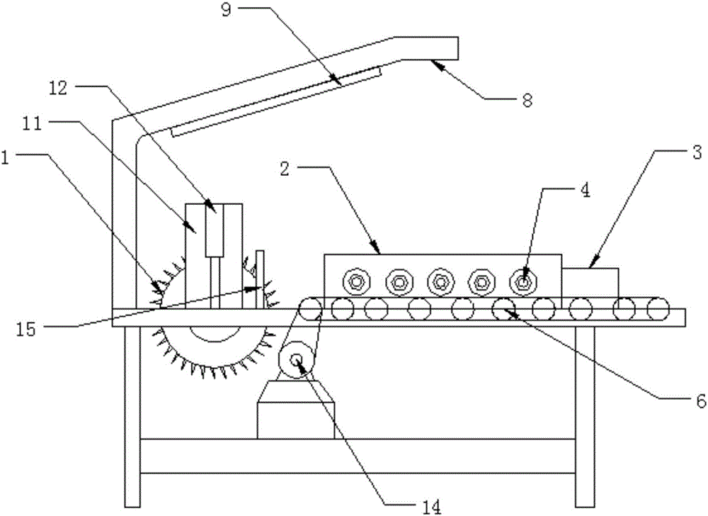
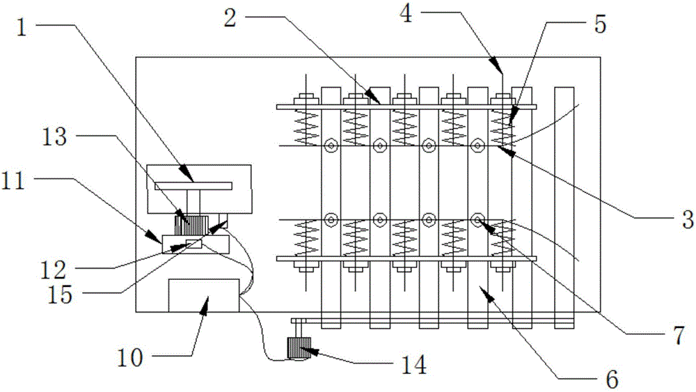
[0026] Such as figure 1 and figure 2 As shown, a kind of automatic cutting equipment comprises a cutting table and an electric saw 1 vertically installed on the cutting table, including a baffle plate 2, a flexible steel plate 3 and a plurality of screw rods 4, and two Baffle 2, two baffles 2 are parallel and symmetrically arranged, the electric saw 1 is installed on the front ends of the symmetrical line of the two baffles 2, and the sides of the two baffles 2 are provided with a plurality of through holes for the screw rod 4 to pass through vertically. The screw rod 4 can slide in the through hole, and the screw rod 4 is sleeved with a compression spring 5 on the inner side of the baffle plate, and the screw rod 4 is fixedly connected to the flexible steel plate 3 at the inner side of the baffle plate 2; One end is fixedly connected with the flexible steel plate 3, and the other end bears against the inner side of the baffle 2; a plurality of rollers 6 are arranged perpend...

Embodiment 2

[0029] Such as figure 1 and figure 2 As shown, a kind of automatic cutting equipment comprises a cutting table and an electric saw 1 vertically installed on the cutting table, including a baffle plate 2, a flexible steel plate 3 and a plurality of screw rods 4, and two Baffle 2, two baffles 2 are parallel and symmetrically arranged, the electric saw 1 is installed on the front ends of the symmetrical line of the two baffles 2, and the sides of the two baffles 2 are provided with a plurality of through holes for the screw rod 4 to pass through vertically. The screw rod 4 can slide in the through hole, and the screw rod 4 is sleeved with a compression spring 5 on the inner side of the baffle plate, and the screw rod 4 is fixedly connected to the flexible steel plate 3 at the inner side of the baffle plate 2; One end is fixedly connected with the flexible steel plate 3, and the other end bears against the inner side of the baffle 2; a plurality of rollers 6 are arranged perpend...

Embodiment 3

[0032] Such as figure 1 and figure 2 As shown, a kind of automatic cutting equipment comprises a cutting table and an electric saw 1 vertically installed on the cutting table, including a baffle plate 2, a flexible steel plate 3 and a plurality of screw rods 4, and two Baffle 2, two baffles 2 are parallel and symmetrically arranged, the electric saw 1 is installed on the front ends of the symmetrical line of the two baffles 2, and the sides of the two baffles 2 are provided with a plurality of through holes for the screw rod 4 to pass through vertically. The screw rod 4 can slide in the through hole, and the screw rod 4 is sleeved with a compression spring 5 on the inner side of the baffle plate, and the screw rod 4 is fixedly connected to the flexible steel plate 3 at the inner side of the baffle plate 2; One end is fixedly connected with the flexible steel plate 3, and the other end bears against the inner side of the baffle 2; a plurality of rollers 6 are arranged perpend...


PUM


Abstract

The invention discloses automated cutting equipment which comprises a cutting table, an electric saw which is vertically mounted, baffles, flexible steel plates and a plurality of screw rods, wherein the two baffles are vertically and fixedly arranged on the working plane of the cutting table in a parallel and symmetric manner; a plurality of through holes allowing the screw rods to penetrate through perpendicularly are formed in the side surfaces of each of the baffles; one section, on the inner sides of the baffles, of each of the screw rods is sleeved with a compressed spring; one end, on the inner sides of the baffles, of each of the screw rods is fixedly connected with the corresponding flexible steel plate; one end of each of the compressed springs is fixedly connected with the corresponding flexible steel plate, and the other ends of the compressed springs are propped against the inner sides of the baffles; a plurality of rollers are arranged in the working plane of the cutting table between the baffles in a manner of being perpendicular to the baffles and are belt driven through a stepping motor; the stepping motor is in electric connection with an intelligent controller; a lifting frame is arranged on the working plane of the cutting table; the driving motor of the electric saw is connected with a telescopic hydraulic rod in the lifting frame; the telescopic hydraulic rod is in electric connection with the intelligent controller; the intelligent controller is in wireless connection with peripheral human-computer interaction equipment.

Description

technical field [0001] The invention relates to a cutting device, in particular to an automatic cutting device. Background technique [0002] Traditional cutting equipment requires manual control of the object to be cut during cutting, and manual control of the feeding of the object to be cut, but manual control of the object to be cut will cause unstable control of the object to be cut, causing hand abrasions during the cutting process, Secondly, it will also cause problems such as deviation of the cutting line of the object to be cut, and uneven cutting surface of the object to be cut. At the same time, the traditional cutting equipment has a fixed cutting tool, which is difficult to adapt to the cutting of objects to be cut in different shapes and sizes. [0003] For example, a cutting machine disclosed in the patent No. CN201620256147.1, the cutting tool is fixed and cannot be moved during processing, it is difficult to adapt to the cutting of objects to be cut in differ...

Claims


Application Information

Patent Timeline
IPC IPC(8): B23D47/04B23D59/00B23Q11/00B23Q11/08
CPCB23D47/04B23D59/00B23Q11/00B23Q11/08
Inventor 谢航洋
Owner 谢航洋
Why Eureka
Try Eureka