
A base mechanism of a spot welding machine

A spot welding machine and spot welding technology, applied in welding equipment, resistance welding equipment, metal processing equipment, etc., can solve problems such as difficult height adjustment, affecting work efficiency, and easy wear of the lower electrode, so as to save debugging fixtures Time, improve production efficiency, welding firm effect

Active Publication Date: 2020-10-02
NINGBO HONGXIECHENG AUTO PARTS CO LTD
View PDF8 Cites 0 Cited by
  • Summary
  • Abstract
  • Description
  • Claims
  • Application Information

AI Technical Summary

Problems solved by technology

In the process of realizing the above spot welding, it is found that the lower electrode of the spot welding machine is easy to wear, which leads to virtual welding in the spot welding process, which directly affects the quality of the product after welding
Although this defect can adjust the height of the lower electrode by adjusting the lower grip bar, it requires frequent adjustments, and it is extremely inconvenient to adjust, and it is not easy to adjust to a suitable height, and this adjustment method is completely dependent on people. high, so there are still hidden dangers of quality accidents
Therefore, in actual production, the phenomenon of virtual welding still cannot be eliminated. At the same time, when the entire spot welding base is spot-welded with arc-shaped products, the operation is troublesome, which seriously affects the work efficiency.

Method used


Image

  • A base mechanism of a spot welding machine
  • A base mechanism of a spot welding machine

Examples


Embodiment Construction

[0021] The following are specific embodiments of the present invention and in conjunction with the accompanying drawings, the technical solutions of the present invention are further described, but the present invention is not limited to these embodiments.

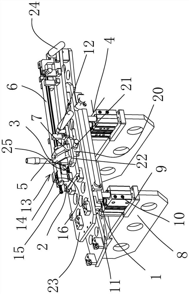
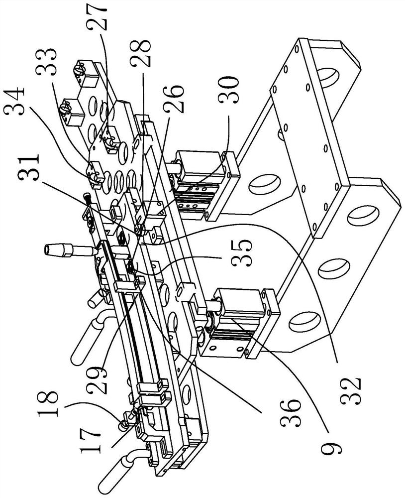
[0022] In the figure, bottom plate 1; product fixing jig part 2; curved surface moving part 3; floating part 4; electrode head 5; automobile guide rail 6; bracket 7; fixed plate 8; floating cylinder 9; cylinder fixed plate 10; nylon block 11 ; fixed block 12; end limit component 13; end limit block 14; adjustment screw 15; locking piece 16; guide rail fork limit block 17; Bracket limit block 20; Bracket lock 21; Limit port 22; Mobile main board 23; Operating handle 24; Mobile auxiliary component 25; Middle rolling component 26; End rolling component 27; 29; side fixing block 30; side roller 31; inclined groove top mouth 32; end fixing block 33; end roller 34; middle roller 35; middle roller 36.

[0023] Such as figure 1 ...


PUM


Abstract

The invention belongs to the technical field of automobile part inspection devices, and provides a base mechanism of a spot welder. The base mechanism comprises a bottom plate, a product fixing jig component, a cambered surface movement component and floating components. The product fixing jig component is arranged on the bottom plate. An electrode tip is arranged at the upper end of the product fixing jig component. The cambered surface movement component is arranged under the product fixing jig component and used for enabling a product to be subjected to spot welding to do cambered surface movement during spot welding. The floating components are arranged on the lower portion of the bottom plate and act on the bottom plate to make the bottom plate float up or down during spot welding so that an impact buffer effect can be achieved. The base mechanism has the advantages that air cylinders float up or down so that the impact buffer effect can be achieved, the mode is widely applied to spot welding production, the jig debugging time is shortened, the qualification rate of spot-welded products is remarkably increased, the production efficiency is greatly improved, meanwhile, the spot welding quality is ensured, quality accidents caused by human factors are avoided, and the base mechanism has the characteristics of being simple in structure, good in universality and low in improvement cost.

Description

technical field [0001] The invention belongs to the technical field of tooling for processing auto parts, and in particular relates to a base mechanism of a spot welding machine. Background technique [0002] Spot welding connection is a commonly used connection method between metal materials. The usual spot welding operations are performed by spot welding machines, and the fixtures of the workpieces to be welded are placed on the working platform of the spot welding machine. In the process of realizing the above-mentioned spot welding, it is found that the lower electrode of the spot welding machine is easy to wear and tear, which leads to false welding in the spot welding process, and then directly affects the quality of the product after welding. Although this defect can adjust the height of the lower electrode by adjusting the lower grip bar, it requires frequent adjustments, and it is extremely inconvenient to adjust, and it is not easy to adjust to a suitable height, a...

Claims


Application Information

Patent Timeline
Patent Type & Authority Patents(China)
IPC IPC(8): B23K11/11
CPCB23K11/11
Inventor 吴明
Owner NINGBO HONGXIECHENG AUTO PARTS CO LTD
Learn More