Automatic assembly device for rotating shaft and spiral fan blade wheels of electronic control motor

An automatic assembly and screw fan technology, applied in metal processing, metal processing equipment, manufacturing tools, etc., can solve the problems that are not suitable for assembly line operation, not suitable for mass production, not automatic production, etc., to achieve compact structure, improve rigidity, The effect of improving the service life

Active Publication Date: 2017-05-31
济宁高新科达科技项目服务有限公司
View PDF7 Cites 2 Cited by
  • Summary
  • Abstract
  • Description
  • Claims
  • Application Information

AI Technical Summary

Problems solved by technology

[0002] At present, the existing electronically controlled motors are equipped with spiral fan wheels at both ends of the rotor shaft. The installation is generally manual assembly. It is necessary to hold the shaft by hand and hit the spiral fan wheel with a rubber hammer to install it. Suitable for mass production, requiring a lot of manpower and material resources
[0003] In addition, the existing electronically controlled motor needs to be pickled after the assembly of the rotating shaft and the spiral fan wheel is completed. Pickling is to put the rotating shaft assembly into the pickling pool in batches, resulting in uneven pickling and heavy workload. It is not suitable for assembly line operation, and it is easy to damage the product; in addition, the cleaning before assembly is also soaked and air-dried, which is inefficient and not automatic production

Method used


Image

  • Automatic assembly device for rotating shaft and spiral fan blade wheels of electronic control motor
  • Automatic assembly device for rotating shaft and spiral fan blade wheels of electronic control motor
  • Automatic assembly device for rotating shaft and spiral fan blade wheels of electronic control motor

Examples


Embodiment Construction

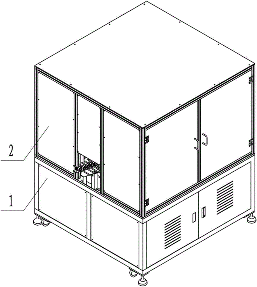
[0046] Such as Figure 1-15 As shown, the automatic assembly device for the rotating shaft of the electronically controlled motor and the spiral fan wheel of this embodiment includes a machine base 1, a working system arranged on the machine base 1, and a shield 2 covering the working system;

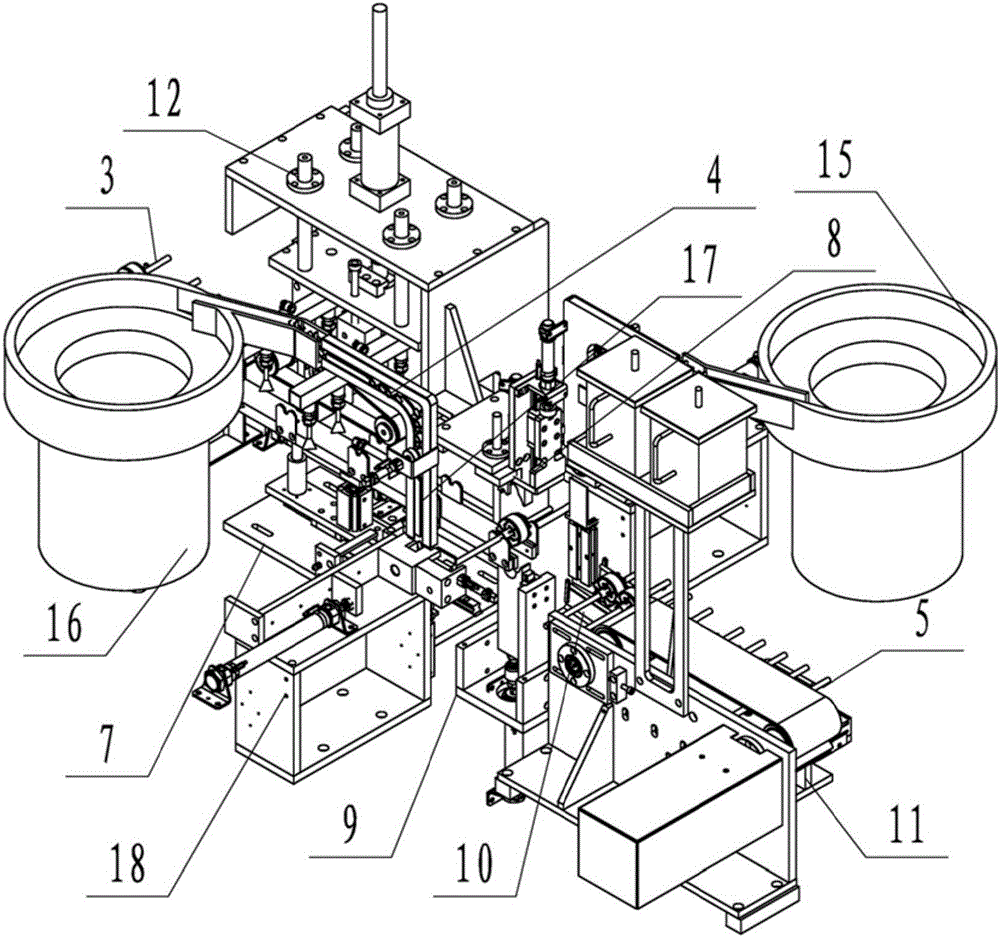
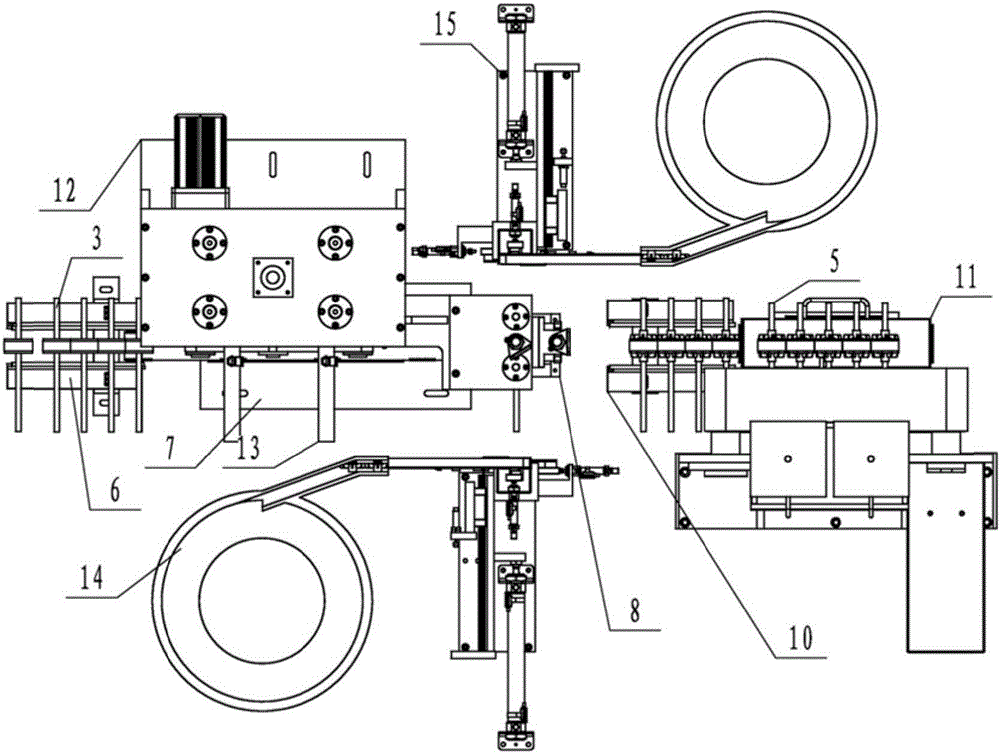
[0047] The working system includes the feeding frame group 6 for placing the central spindle 3 to be assembled, the feeding device 7 connected with the feeding device group 6 process, the transition frame group 10 connected with the feeding device 7 process, and the transition frame group 10 process The connected pickling device 11, the rotary drive device 12 arranged on one side of the feeding device 7, the spray frame 13 with the nozzles above the two ends of the central spindle 3 placed on the feeding device 7, and two sets respectively On both sides of the feeding device 7, the first vibrating feeding device 14 and the second vibrating feeding device 15 of the spiral fan wheel 4 are...


PUM


Abstract

The invention relates to an automatic assembly device for a rotating shaft and spiral fan blade wheels of an electronic control motor. The automatic assembly device comprises a machine base, a working system arranged on the machine base and a protective cover arranged on the working system in a covering mode; the working system comprise a feed frame group carrying a center spindle to be assembled, a feeding device connected with the feed frame group process, a transition frame group connected with the feeding device process, an acid pickling device connected with the transition frame group process, a rotating driving device arranged at one side of the feeding device, a spray frame of which nozzles are located over spindle heads at the two ends of the center spindle placed on the feeding device, a first vibration feeding device, a second vibration feeding device, a jacking frame group and a rising frame group, wherein the first vibration feeding device and the second vibration feeding device are arranged at the two sides of the feeding device and each provided with one spiral fan blade wheel, and the jacking frame group and the rising frame group are located between the feeding device and the transition frame group. The automatic assembly device is reasonable in design, compact in structure and convenient to use.

Description

technical field [0001] The invention relates to an automatic assembly device for a rotating shaft of an electric control motor and a spiral fan wheel. Background technique [0002] At present, the existing electronically controlled motors are equipped with spiral fan wheels at both ends of the rotor shaft. The installation is generally manual assembly. It is necessary to hold the shaft by hand and hit the spiral fan wheel with a rubber hammer to install it. It is suitable for mass production and requires a lot of manpower and material resources. [0003] In addition, the existing electronically controlled motor needs to be pickled after the assembly of the rotating shaft and the spiral fan wheel is completed. Pickling is to put the rotating shaft assembly into the pickling pool in batches, resulting in uneven pickling and heavy workload. It is not suitable for assembly line operation, and it is easy to damage the product; in addition, the cleaning before assembly is also so...

Claims


Application Information

Patent Timeline
IPC IPC(8): B23P19/00
CPCB23P19/00
Inventor 沈祥明
Owner 济宁高新科达科技项目服务有限公司
Why Eureka
Try Eureka