Quick-cleaning multi-stage automatic parts assembly machine for motor rotor shafts

A motor rotor and assembly machine technology, applied in metal processing, metal processing equipment, manufacturing tools, etc., can solve the problems of reduced processing efficiency, installation offset, waste of processing time, etc.

Active Publication Date: 2017-05-31
周胡琴
View PDF8 Cites 6 Cited by
  • Summary
  • Abstract
  • Description
  • Claims
  • Application Information

AI Technical Summary

Problems solved by technology

In order to make the motor rotor shaft have better functionality, after the motor rotor shaft is processed, it is necessary to install some assembly parts on the motor rotor shaft, such as sealing rings, gears, etc. The traditional installation method is to manually place it on the punching machine After installing one component, collect and move it to the next station to install another component. On the one hand, it wastes processing time and reduces processing efficiency. On the other hand, it is manually placed on the tooling of the punching machine vertically, which is very easy to Place the offset, after the offset, it will cause the installation offset

Method used


Image

  • Quick-cleaning multi-stage automatic parts assembly machine for motor rotor shafts
  • Quick-cleaning multi-stage automatic parts assembly machine for motor rotor shafts
  • Quick-cleaning multi-stage automatic parts assembly machine for motor rotor shafts

Examples


Embodiment Construction

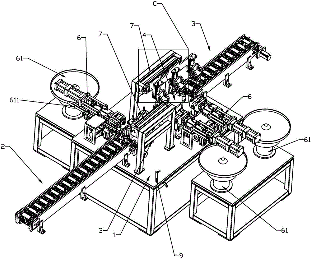
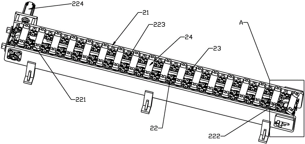
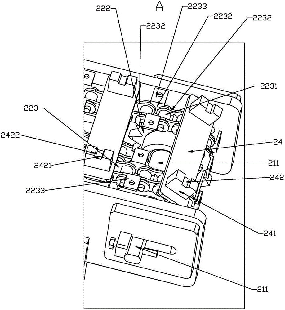
[0034] Such as figure 1 — Figure 11 As shown, the present invention discloses a fast-cleaning multi-stage automatic assembly machine for motor rotor shaft components, including a working table 1, on which a feeding device 2, a first processing seat 3, and a second processing seat 4 are sequentially arranged And the discharge device 5, the working surface 1 is located on the side of the first processing seat 3 and the second processing seat 4, and an assembly device 6 is provided. Between the feeding device 2 and the first processing seat 3, a motor rotor shaft is arranged to switch positions in sequence. The front transport device 7, the rear transport device 8 that switches the position of the motor rotor shaft sequentially between the first processing seat 3, the second processing seat 4 and the discharge device 5, the feed device 2 and the discharge device 5 respectively include Track support 21, left gear belt assembly 22, right gear belt assembly 23 and several motor ro...


PUM


Abstract

The invention relates to a quick-cleaning multi-stage automatic parts assembly machine for motor rotor shafts, comprising a work tabletop; a feeding unit, a first processing base, a second processing base and a discharging unit are arranged sequentially on the work tabletop; the work tabletop is provided with an assembly unit on the lateral side of the first and second processing bases, a front conveyer for changing the position of a motor rotor shaft in sequence is arranged between the feeding unit and the first processing base, and a cleaning mechanism is arranged on the work tabletop. The quick-cleaning multi-stage automatic parts assembly machine for motor rotor shafts according to the above scheme can keep the tabletop clean.

Description

technical field [0001] The invention relates to a processing equipment for a motor rotor shaft, in particular to a fast-cleaning automatic assembly machine for multi-stage components of a motor rotor shaft. Background technique [0002] The motor rotor shaft is a transliteration of the English motor, that is, the motor and the engine. The working principle is to drive the starter rotor to rotate through electromagnetic induction, and the pinion on the rotor drives the engine flywheel to rotate. In order to make the motor rotor shaft have better functionality, after the motor rotor shaft is processed, it is necessary to install some assembly parts on the motor rotor shaft, such as sealing rings, gears, etc. The traditional installation method is to manually place it on the punching machine After installing one component, collect and move it to the next station to install another component. On the one hand, it wastes processing time and reduces processing efficiency. On the o...

Claims


Application Information

Patent Timeline
Patent Type & Authority Applications(China)
IPC IPC(8): B23P19/027B23P19/00
CPCB23P19/004B23P19/027
Inventor 周胡琴
Owner 周胡琴
Why Eureka
Try Eureka