An automatic continuous assembly and orderly output equipment
A technology of output equipment and output mechanism, which is applied in the direction of metal processing equipment, metal processing, manufacturing tools, etc., can solve the problem of inability to automatically assemble and combine product parts, orderly output of products, and achieve the effect of simplifying the number of equipment
- Summary
- Abstract
- Description
- Claims
- Application Information
AI Technical Summary
Problems solved by technology
Method used
Image
Examples
Embodiment 1
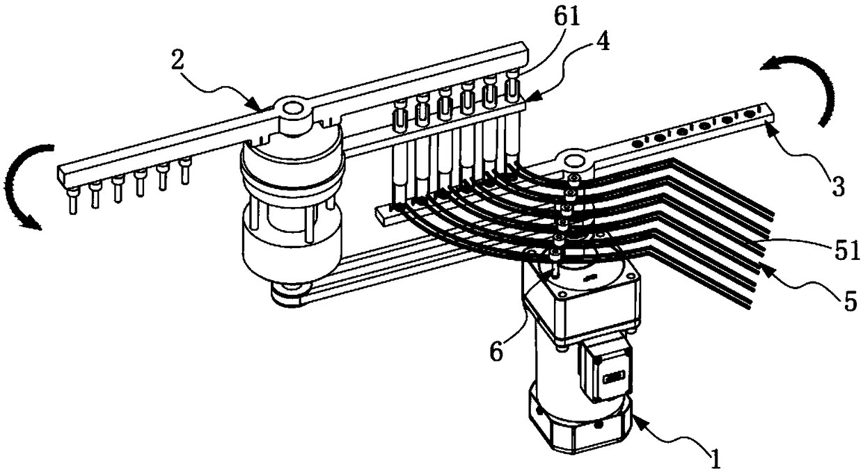
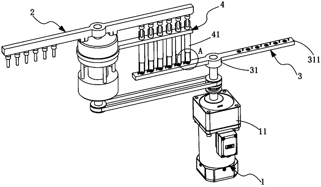
[0059] like figure 1 As shown, an automatic continuous assembly and orderly output device is characterized in that it includes a drive mechanism 1, a first rotary feed mechanism 2, a second rotary feed mechanism 3, an assembly guide mechanism 4 and an orderly output mechanism 5 , the first rotary feed mechanism 2 is arranged on the front side of the drive mechanism 1, the second rotary feed mechanism 3 is installed on the drive mechanism 1, and the first rotary feed mechanism 2 and the second The rotary feeding mechanism 3 is driven synchronously by the driving mechanism 1, the assembly guiding mechanism 4 is sleeved on the first rotary feeding mechanism 2, and the rear side of the assembling guiding mechanism 4 is provided with the orderly output mechanism 5. The first rotary feeding mechanism 2 and the second rotary feeding mechanism 3 respectively synchronously rotate and transport the product part A61 and the product part B62 to the top and bottom of the assembly guide mec...
Embodiment approach
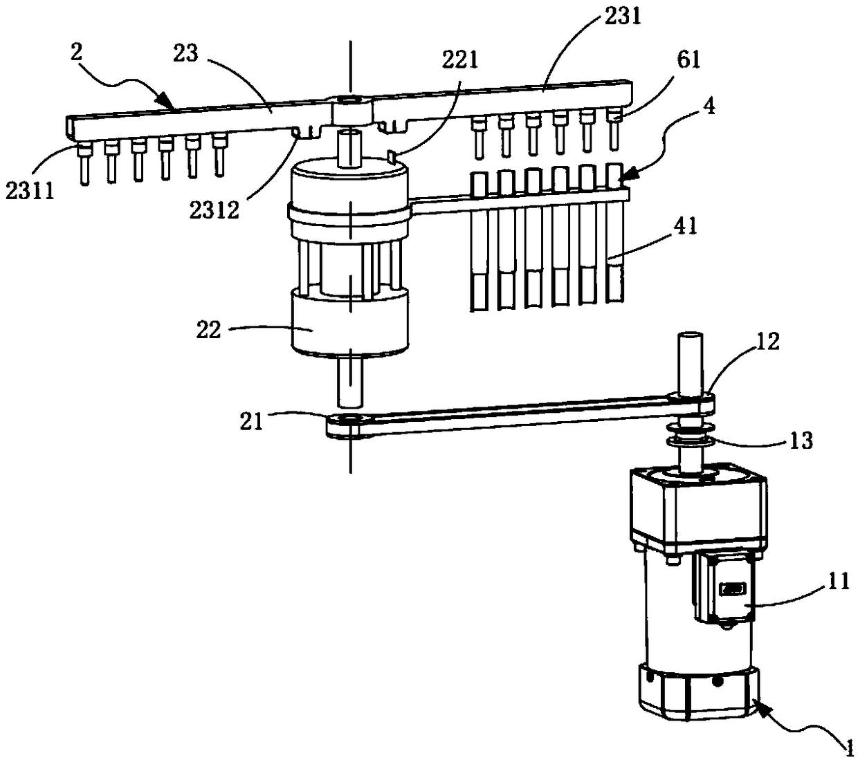
[0067] like figure 2 As shown, as a preferred embodiment, the drive mechanism 1 includes:
[0068] drive motor 11;
[0069] The first driving pulley 12, the first driving pulley 12 is installed on the motor shaft of the drive motor 11; and
[0070] The second driving pulley 13 is installed on the motor shaft of the driving motor 11 and is located below the first driving pulley 12 .
[0071] Further, the first rotary feeding mechanism 2 also includes:
[0072] The first driven pulley 21, the first driven pulley 21 is connected with the first driving pulley 12 by a belt;
[0073] The rotator 22, the rotator 22 is arranged above the first driven pulley 21, it rotates synchronously with the first driven pulley 21, and the rotator 22 is provided with an insulating sheet facing the assembly guide mechanism 4 221; and
[0074] The adsorption assembly 23 is arranged on the upper end of the rotator 22, and the lower end surface of the adsorption unit 231 is linearly arrayed with ...
Embodiment 2
[0080] Figure 7 , Figure 8 , Figure 9 and Figure 10 It is a structural schematic diagram of Embodiment 2 of an automatic continuous assembly and orderly output device of the present invention; Figure 7 As shown, the parts that are the same as or corresponding to those in Embodiment 1 use the reference numerals corresponding to Embodiment 1. For the sake of simplicity, only the differences from Embodiment 1 will be described below. The difference between this embodiment two and embodiment one is:
[0081] like Figure 7 As shown, an automatic continuous assembly and ordered output device also includes a first sorting mechanism 7 for automatically sorting the messy and disordered product parts A61, and the first sorting mechanism 7 includes:
[0082] The input assembly 71, the input assembly 71 is located at the front end of the first rotary feeding mechanism 2, and it is used to input the disordered product parts A61; and
[0083] The sorting box 72, the sorting box ...
PUM
 Abstract
Description
Claims
Application Information
 - R&D
- Intellectual Property
- Life Sciences
- Materials
- Tech Scout
- Unparalleled Data Quality
- Higher Quality Content
- 60% Fewer Hallucinations
Browse by: Latest US Patents, China's latest patents, Technical Efficacy Thesaurus, Application Domain, Technology Topic, Popular Technical Reports.
© 2025 PatSnap. All rights reserved.Legal|Privacy policy|Modern Slavery Act Transparency Statement|Sitemap|About US| Contact US: help@patsnap.com


