Turning blade service life comparison method

An insert and turning technology, applied in the field of turning insert service life comparison, can solve the problems of poor economy, low efficiency, serious tool wear, etc., to reduce costs, improve test efficiency, and save test time.

Inactive Publication Date: 2017-05-31
ZHUZHOU CEMENTED CARBIDE CUTTING TOOLS CO LTD
View PDF5 Cites 6 Cited by
  • Summary
  • Abstract
  • Description
  • Claims
  • Application Information

AI Technical Summary

Problems solved by technology

The disadvantage of this method is that the cutting test takes a long time, the efficiency is low, it is difficult to quickly test the life of the turning insert in the actual cutting test, and the wear of the tool is serious, and the economy is poor

Method used


Image

  • Turning blade service life comparison method
  • Turning blade service life comparison method
  • Turning blade service life comparison method

Examples


Embodiment Construction

[0025] The present invention will be further described in detail below in conjunction with the accompanying drawings and specific embodiments.

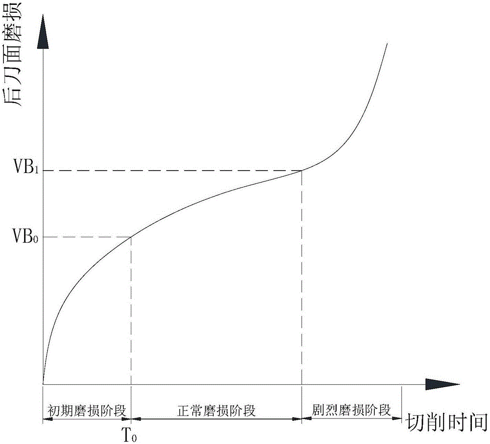
[0026] Turning blade service life comparison method of the present invention, compare the service life length of each turning blade by comparing the initial wear rate K of each turning blade, the initial wear rate K 0 Obtained by the following steps:

[0027] S1. Set initial wear cutting time T 0 ;

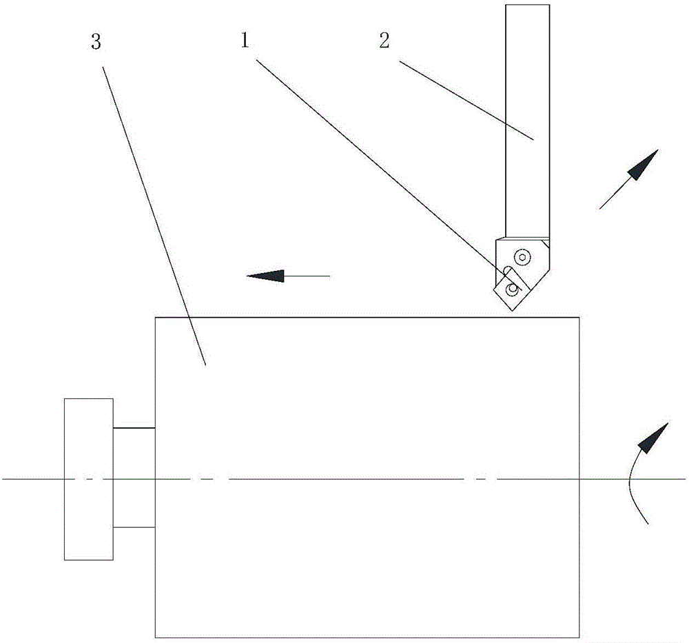
[0028] S2. Turn on the cutting machine tool, and cut the workpiece according to the set cutting speed Vc, feed rate f and depth of cut ap;

[0029] S3, the cutting time reaches the initial wear cutting time T 0 back knife;

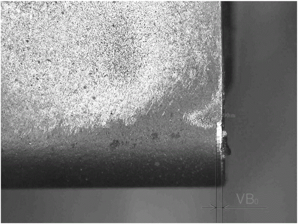
[0030] S4. Measure the initial wear value VB of the main flank surface of the turning insert 0 ;

[0031] S5, according to K 0 =VB 0 / T 0 Calculate the initial wear rate K of the turning insert 0 .

[0032] Make each turning insert 1 follow the same cutting parameters and the same initial wear cutting time ...


PUM


Abstract

The invention discloses a turning blade service life comparison method. Service life length of each turning blade can be compared according to comparisons of primary wear rate K0 of each turning blade. The primary wear rate K0 can be acquired via the following steps that (S1) primary wear cutting time is set to be T0; (S2), a cutting machine is started and cuts a work piece according to a preset cutting speed Vc, feeding load f and cutting depth ap; (S3) the blade retreats when the cutting time reaching the primary wear cutting time T0; (S4) primary wear value VB0 of a main back blade surface of the turning blade is measured; and (S5), primary wear rate K0 of the turning blade is calculated according to a formula of K0=VB0 / T0. The turning blade service life comparison method is advantaged by simple operation, high feasibility and short time consumption.

Description

technical field [0001] The invention relates to the technical field of metal cutting, in particular to a method for comparing service life of turning inserts. Background technique [0002] Turning tools are widely used in general cylindrical cutting, profiling cutting and face cutting, and insert life is a very important cutting performance index. [0003] like figure 1 As shown, the normal wear of the main flank of the ordinary turning insert is divided into three stages: initial wear stage, normal wear stage and severe wear stage. The actual contact area between the flank face of the new insert and the machined surface is very small, and the pressure is very This is the initial wear stage of ordinary turning inserts; in the normal wear stage, a narrow edge is ground on the flank surface, and the pressure decreases, so the increase in wear tends to be stable. This stage is The effective stage of tool work; the severe wear stage is that after the normal wear of the tool, t...

Claims


Application Information

Patent Timeline
Patent Type & Authority Applications(China)
IPC IPC(8): B23Q17/09
CPCB23Q17/0995
Inventor 吕天宝黄威武罗胜汤爱民王社权
Owner ZHUZHOU CEMENTED CARBIDE CUTTING TOOLS CO LTD
Why Eureka
Try Eureka