Automatic grinding fixture for numerical-control machine tool

A CNC machine tool and grinding technology, which is applied in the direction of grinding workpiece supports, etc., can solve the problems of jig hesitation, labor waste, time-consuming and labor-intensive, etc., and achieve the effect of improving detection accuracy, detection accuracy, and enhancing stability

Active Publication Date: 2017-05-31
威海威硬工具股份有限公司
View PDF11 Cites 2 Cited by
  • Summary
  • Abstract
  • Description
  • Claims
  • Application Information

AI Technical Summary

Problems solved by technology

However, although the numerical control of the grinding equipment, especially the feed axis, has been perfected, the supporting fixtures are still stagnant, and workers still need to clamp a single piece to adjust the positioning of the workpiece, which is time-consuming and laborious, and it varies from person to person. Processing error
Therefore, the automation and precision of the fixture has become the main problem that is difficult to overcome at present, especially for multiple workpieces that need to be ground symmetrically on both sides, the labor waste is serious

Method used


Image

  • Automatic grinding fixture for numerical-control machine tool
  • Automatic grinding fixture for numerical-control machine tool
  • Automatic grinding fixture for numerical-control machine tool

Examples


Embodiment Construction

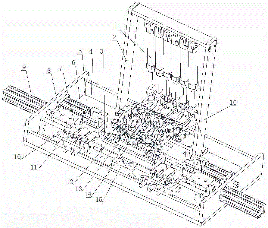
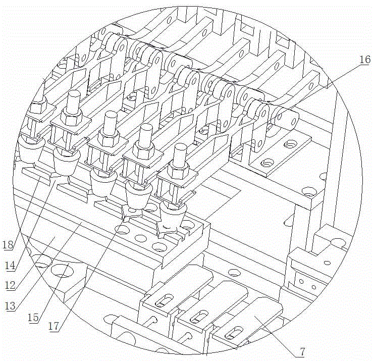
[0018] As shown in the figure, the automatic grinding fixture for CNC machine tools is provided with a mounting plate 5, and the middle part of the mounting plate 5 is provided with a 180° rotary cylinder 15, and the turntable of the rotary cylinder 15 is provided with a mold clamping seat 12, and the mold clamping The seat 12 is provided with a positioning mold, and the positioning mold is provided with a workpiece embedding groove 14; the structure of the positioning mold is: a connecting seat 13 is provided, and the connecting seat 13 is provided with a rectangular positioning plate 18 for installing workpieces to be processed , on the positioning plate 18, a row of open workpiece embedding grooves 14 is uniformly processed longitudinally, and the front and rear sides of the positioning plate 18 are provided with processing openings, from figure 2It can be seen from the figure that the positioning plate 18 is divided into sections by the workpiece embedding groove and the p...


PUM


Abstract

The invention discloses an automatic grinding fixture for a numerical-control machine tool, and relates to the technical field of auxiliary accessories for numerical-control machining. The automatic grinding fixture is provided with a mounting plate. A rotary cylinder is arranged on the mounting plate, a die clamping seat is arranged on the rotary cylinder, positioning dies are arranged on the die clamping seat, and workpiece embedding grooves are formed in the positioning dies; a reference positioning slide rail is arranged on the mounting plate, positioning sliders are arranged on the reference positioning slide rail, reference positioning blocks are arranged on the positioning sliders, reference positioning cylinders are arranged on the mounting plate, piston rods of the reference positioning cylinders are connected with the positioning sliders, detection yielding cylinders are arranged on the mounting plate, detection positioning cylinders are arranged on the detection yielding cylinders, displacement detection frames are arranged on piston rods of the detection positioning cylinders, and displacement detection devices are arranged on the displacement detection frames; pliers are arranged on the mounting plate and are positioned at the rear side of the die clamping seat, jaws of the pliers are positioned above the workpiece embedding grooves, a support frame is arranged on the mounting plate, pliers driving cylinders are arranged on the support frame, and piston rods of the pliers driving cylinders are hinged to handles of the pliers. The automatic grinding fixture has the advantages that the automatic grinding fixture is simple in structure, convenient to use and high in production efficiency, and the labor intensity can be relieved.

Description

technical field [0001] The invention relates to the technical field of auxiliary accessories for numerical control machining, and in detail is an automatic grinding fixture for numerical control machine tools with simple structure, high degree of automation, convenient use, high positioning and repeat positioning accuracy, reduced labor intensity and high production efficiency. Background technique [0002] Currently, grinding or grooving of workpieces is usually accomplished by manual clamping close to the grinding wheel. During the grinding process, repeated measurements are required to ensure the processing requirements. This method not only increases the labor intensity of the staff, but also depends on the experience of the staff to determine the amount of grinding during the grinding process, thereby reducing the accuracy of clamping positioning and repeated positioning, and it is difficult to maintain the consistency of multiple workpieces. , and reduce the processin...

Claims


Application Information

Patent Timeline
IPC IPC(8): B24B41/06
CPCB24B41/067
Inventor 于乔赵乐李晓
Owner 威海威硬工具股份有限公司
Why Eureka
Try Eureka