Rotary machining bearing device

A technology of bearing device and rotary processing, which is applied in the direction of grinding workpiece support, etc., to achieve the effect of convenient operation, improved efficiency and precision, and improved convenience

Active Publication Date: 2017-05-31
JIANGSU PULONG MAGNETIC ELECTRICITY CO LTD
View PDF7 Cites 5 Cited by
  • Summary
  • Abstract
  • Description
  • Claims
  • Application Information

AI Technical Summary

Problems solved by technology

[0003] The purpose of the present invention is to provide a rotating processing bearing device with reasonable structure and adjustment according to different parts, aiming to solve the technical deficiency that the parts cannot be quickly clamped and positioned in the traditional technology

Method used


Image

  • Rotary machining bearing device

Examples


Embodiment 1

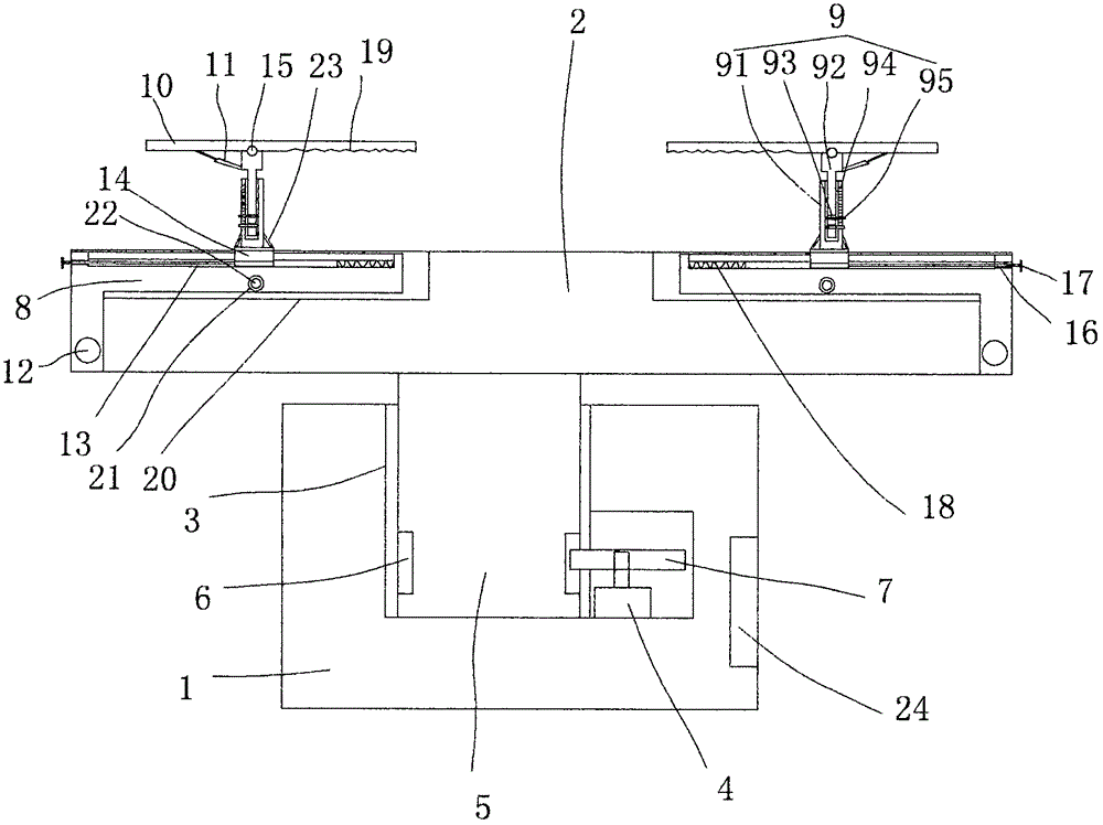
[0017] figure 1 A specific embodiment of the invention is shown in which figure 1 It is a structural schematic diagram of the present invention.

[0018] See figure 1 , a rotating processing bearing device, comprising a base 1, a bearing platform 2 arranged on the top surface of the base 1, at least two quick clamp positioning structures are uniformly arranged on the bearing platform, and a A cavity 3 with an opening on the top surface, a motor 4 is fixed in the cavity 3, a shaft 5 is fixed at the center of the bottom surface of the carrying platform 2, the shaft 5 is inserted into the cavity 3, and the shaft 5 is inserted into the cavity 3. There are tooth grooves 6 on the surface of the shaft 5, and a drive gear 7 is fixed on the main shaft of the motor 4. The drive gear 7 meshes with the tooth grooves 6 on the surface of the shaft. The quick clamp positioning structure It includes an L-shaped bottom bar 8, a telescopic pole 9, a transverse splint 10 and a clamping cylind...


PUM


Abstract

The invention discloses a rotary machining bearing device. The rotary machining bearing device comprises a base, a bearing platform, and at least two fast-clamping positioning mechanisms; a concave cavity with the top surface open is formed in the base, a motor is fixed into the concave cavity, a shaft rod is fixed to the center of the bottom face of the bearing platform, a tooth groove is formed in the surface of the shaft rod, and a driving gear is fixed to a main shaft of the motor; and each fast-clamping positioning mechanism comprises an L-shaped bottom rod, a telescopic pillar rod, a horizontal clamping plate and a clamping pressing air cylinder, wherein the vertical rod bottom end of the L-shaped bottom rod is connected to the edge of the bearing platform through a rotary shaft, a movable T-shaped groove is formed in the horizontal rod side surface of the L-shaped bottom rod, a T-shaped block is fixed to the bottom end of the telescopic pillar rod, and the middle of the horizontal clamping plate is connected to the top of the telescopic pillar rod through a movable shaft. According to the rotary machining bearing device, the installation of the structure is reasonable, operation of the rotary machining bearing device is convenient, the clamping positioning speed is high, and meanwhile, the bearing platform can rotate through the motor, and consequently, convenience of grinding can be greatly improved, using stability is good, and adaptability is high.

Description

technical field [0001] The invention belongs to the technical field of mechanical processing equipment, and in particular relates to a rotating processing bearing device. Background technique [0002] With the maturity of mechanical processing technology in our country, more and more parts are processed. However, due to the fact that some parts may have insufficient precision in the actual processing process, if the CNC machine tool is used for re-processing at this time, not only will the A lot of time is wasted, and it will also greatly increase the production cost. Therefore, in the traditional technology, when the precision of the parts is not enough in several places, most of them use manual hand-held mechanical grinding. Because some parts are large in size and heavy in weight, manual work is required. Moving will greatly increase the cost of grinding and the labor intensity of processing operators. In order to solve the above problems, some simple rotating disks are u...

Claims


Application Information

Patent Timeline
Patent Type & Authority Applications(China)
IPC IPC(8): B24B41/06
CPCB24B41/06
Inventor 周庆川
Owner JIANGSU PULONG MAGNETIC ELECTRICITY CO LTD
Why Eureka
Try Eureka