
Wiring robot of automatic wiring machine

A wiring machine and robot technology, applied in the direction of manipulators, cable laying equipment, manufacturing tools, etc., can solve the problems of inflexible movement and insufficient freedom, and achieve the effects of strong line control, simplified structure, and flexible wiring

Active Publication Date: 2017-05-31
CHANGCHUN UNIV OF SCI & TECH +1
View PDF30 Cites 9 Cited by
  • Summary
  • Abstract
  • Description
  • Claims
  • Application Information

AI Technical Summary

Problems solved by technology

The above-mentioned line-scribing robot uses the X, Y, and Z axes to control the movement separately, and the degree of freedom is not enough and the movement is not flexible.

Method used


Image

  • Wiring robot of automatic wiring machine
  • Wiring robot of automatic wiring machine
  • Wiring robot of automatic wiring machine

Examples


Embodiment Construction

[0026] Below in conjunction with accompanying drawing, introduce technical scheme of the present invention in detail:

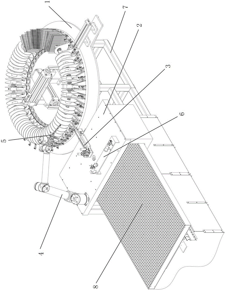
[0027] Such as figure 1 As shown, an aircraft wiring harness automatic wiring machine includes a material warehouse 1, a slide table 2, an automatic wire feeder 3, an automatic wiring machine wiring robot 4, an optical line number recognition and meter counter 6, a connecting frame 7, and a workbench 8 , PC. The material warehouse 1 is installed on the connecting frame 7, the working table 8 is installed on the front end of the connecting frame 7, the sliding table 2 is slidably connected on the working table 8, and it can slide along the slide rail of the working table 8 on the working table 8, and the automatic wiring machine The wiring robot 4 is installed on the slide table 2. The automatic wiring machine The wiring robot 4 is composed of a six-degree-of-freedom mechanical arm and a multi-functional manipulator 5. The automatic wire feeder 3 is installed...


PUM


Abstract

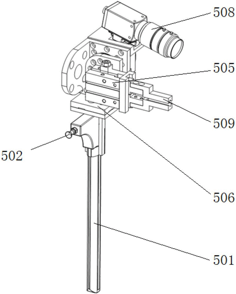
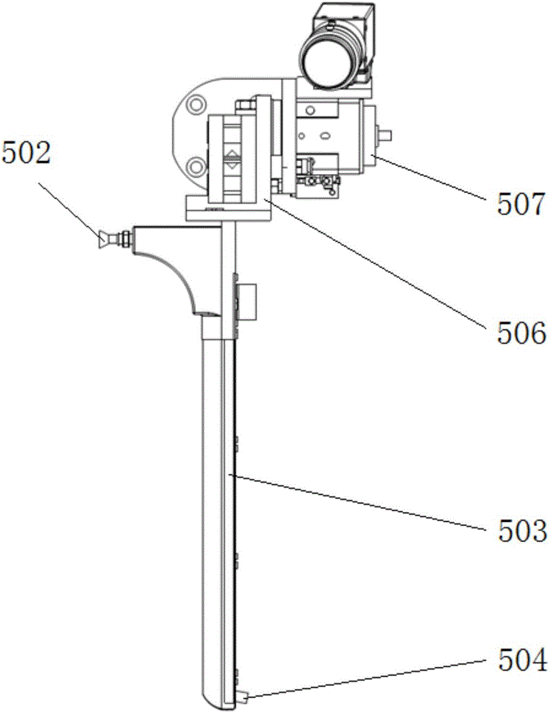
The invention discloses a wiring robot of an automatic wiring machine. The wiring robot comprises a six-freedom-degree mechanical arm and a multifunctional mechanical hand mounted at the end of the six-freedom-degree mechanical arm. The multifunctional mechanical hand comprises a wiring head, a grabbing head, a switching mechanism, a switching drive motor and a vidicon. The wiring head and the grabbing head are fixed to the bottom face and the inner side face of the switching mechanism correspondingly, and the position of the wiring head is perpendicular to that of the grabbing head. The switching drive motor is connected to the outer side face of the switching mechanism, and the switching mechanism is driven by a drive shaft of the switching drive motor to rotate. A pneumatic clamping jaw is arranged at the end of the grabbing head. The wiring head is overall of a hollow structure, a wiring channel is arranged in the wiring head, a wire inlet is formed in the upper end of the wiring channel in the direction perpendicular to the wiring channel, and a wire outlet is formed in the other end of the wiring channel. The vidicon is fixed above the switching drive motor through a connecting plate and located at the top of the multifunctional mechanical hand. The wiring robot is high in circuit controllability and flexible in wiring, and material taking and wiring can be completed through the mechanical hand.

Description

technical field [0001] The invention relates to an automatic wiring machine wiring robot, which belongs to the field of aircraft manufacturing equipment. Background technique [0002] Domestic aircraft wiring harnesses are mostly wired manually. Due to the large number of cables on the aircraft, and with the continuous enrichment of aircraft functions, the electrical system of the aircraft has become more and more complex. The number of cables on the aircraft has increased sharply, and manual wiring requires a lot of manpower. , At the same time, the operator needs to have high technical ability, and the operation is cumbersome and error-prone. Therefore, there is an urgent need for a fully automatic wiring device for aircraft wiring harnesses. [0003] The invention patent application with the application number of 20141023402 discloses an automatic wiring system and wiring method for aircraft cable harnesses, which can realize machine wiring of aircraft wiring harnesses. ...

Claims


Application Information

Patent Timeline
Patent Type & Authority Applications(China)
IPC IPC(8): B25J11/00B25J19/04H02G1/06
CPCH02G1/06B25J11/00B25J19/04
Inventor 曹国华李丽娟陈雪梅田春林姜涛于正林乔晓利梁嵬马国庆贾冰
Owner CHANGCHUN UNIV OF SCI & TECH
Learn More