High-rigidity joint torque sensor

A joint torque and sensor technology, applied in the field of torque measurement, can solve problems such as poor output signal quality, and achieve the effect of improving control accuracy, good quality, high radial force and axial force interference ability

Inactive Publication Date: 2017-05-31
HARBIN INST OF TECH
View PDF5 Cites 18 Cited by
  • Summary
  • Abstract
  • Description
  • Claims
  • Application Information

AI Technical Summary

Problems solved by technology

[0005] In order to solve the problem that the existing joint torque sensor is easily interfered by the radial force and axial force of the harmonic reducer, resulting in poor output signal quality, the present invention proposes a joint torque sensor with high stiffness

Method used


Image

  • High-rigidity joint torque sensor
  • High-rigidity joint torque sensor

Examples


Embodiment 1

[0017] Embodiment one: the following combination figure 1 and figure 2 This embodiment will be described in detail.

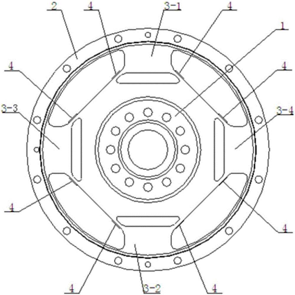
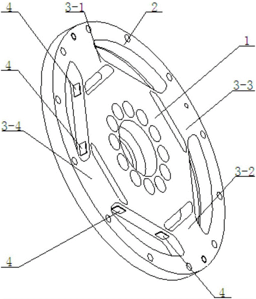
[0018] The high-stiffness joint torque sensor described in this embodiment includes a torque input disk 1, a torque output disk 2, four strain beams and eight strain gauges 4;

[0019] The four strain beams are respectively a first strain beam 3-1, a second strain beam 3-2, a third strain beam 3-3 and a fourth strain beam 3-4, and the first strain beam 3-1, Both ends of the second strain beam 3-2, the third strain beam 3-3 and the fourth strain beam 3-4 are fixedly connected with the outer edge of the torque input disk 1 and the inner edge of the torque output disk 2 respectively, so that The first strain beam 3-1, the second strain beam 3-2, the third strain beam 3-3 and the fourth strain beam 3-4 are evenly distributed along the circumferential direction of the moment input disc 1;

[0020] On the strain beam, the two surfaces that are not parallel to the...

Embodiment 2

[0026] Embodiment 2: This embodiment further limits the high-stiffness joint torque sensor described in Embodiment 1.

[0027] In the high-stiffness joint torque sensor described in this embodiment, the strain gauge 4 is a metal foil resistance strain gauge.

[0028] The metal foil resistance strain gauge has small transverse effect, good heat dissipation performance, large current allowed to pass through, good flexibility, small creep and long fatigue life.


PUM


Abstract

The invention discloses a high-rigidity joint torque sensor, belongs to the field of torque measurement, and solves the problem of weak output signal quality caused by easy influence on a traditional joint torque sensor by the radial force and the axial force of a harmonic reducer. The sensor comprises a torque input disc, a torque output disc, four strain beams and eight strain pieces; two ends of the strain beams are fixedly connected with the outer edge of the torque input disc and the inner edge of the torque output disc as a whole; and the four strain beams are uniformly distributed in the peripheral direction of the torque input disc. Two surfaces, not parallel to the end surface of the torque input disc, of the strain beams are two side surfaces; and the strain pieces are respectively arranged on the two side surfaces of the strain beams. The strain pieces on the first and second strain beams form a first full-bridge measurement circuit; the strain pieces on the third and fourth strain beams form a second full-bridge measurement circuit; and when the sensor detects a joint output torque, the stress directions of the strain pieces are tangential to the rotating direction of the sensor. The sensor is used for detecting the joint output torque.

Description

technical field [0001] The invention relates to a high-rigidity joint torque sensor, which belongs to the field of torque measurement. Background technique [0002] Harmonic reducers are widely used in the drive mechanisms of manipulators and robot joints because of their light weight, small size, large reduction ratio, high efficiency, and small return stroke difference. In the process of the manipulator grasping an object or the manipulator arm completing a specific action, the control system can realize precise control of the torque according to the feedback signal of the joint torque sensor. [0003] The existing shear joint torque sensor has poor stiffness because the strain gauges are arranged on the side of the strain beam parallel to the end face of the torque input disk. In the existing tension-compression joint torque sensor, the strain gauges are arranged on the side of the strain beam that is not parallel to the end face of the torque input disk. Compared with t...

Claims


Application Information

Patent Timeline
Patent Type & Authority Applications(China)
IPC IPC(8): B25J13/08G01L3/00
CPCB25J13/085G01L3/00
Inventor 史士财何庆超王达孙奎刘宏
Owner HARBIN INST OF TECH
Why Eureka
Try Eureka