Turning to multi-wire cutting method and equipment

A multi-wire cutting and multi-wire cutting machine technology, applied in the field of mechanical processing, can solve the problems of increased material turnover time and long time, and achieve the effects of improving product quality, reducing the probability of defects, and shortening material turnover time.

Active Publication Date: 2019-02-19
京磁材料科技股份有限公司
View PDF5 Cites 0 Cited by
  • Summary
  • Abstract
  • Description
  • Claims
  • Application Information

AI Technical Summary

Problems solved by technology

The process of removing glue and oil takes a long time, which increases the turnover time of materials. At the same time, because magnetic materials, especially NdFeB magnetic materials, have hard and brittle physical properties, they are difficult to process during slicing, grinding, and glue and oil removal. Repeated transfers between the two processes greatly increase the probability of causing collapse, broken and other poor appearance

Method used


Image

  • Turning to multi-wire cutting method and equipment
  • Turning to multi-wire cutting method and equipment
  • Turning to multi-wire cutting method and equipment

Examples


Embodiment 1

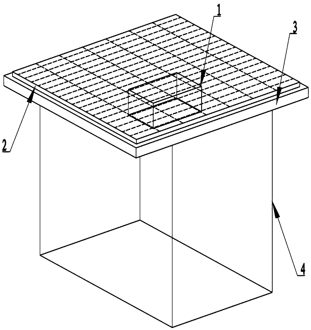
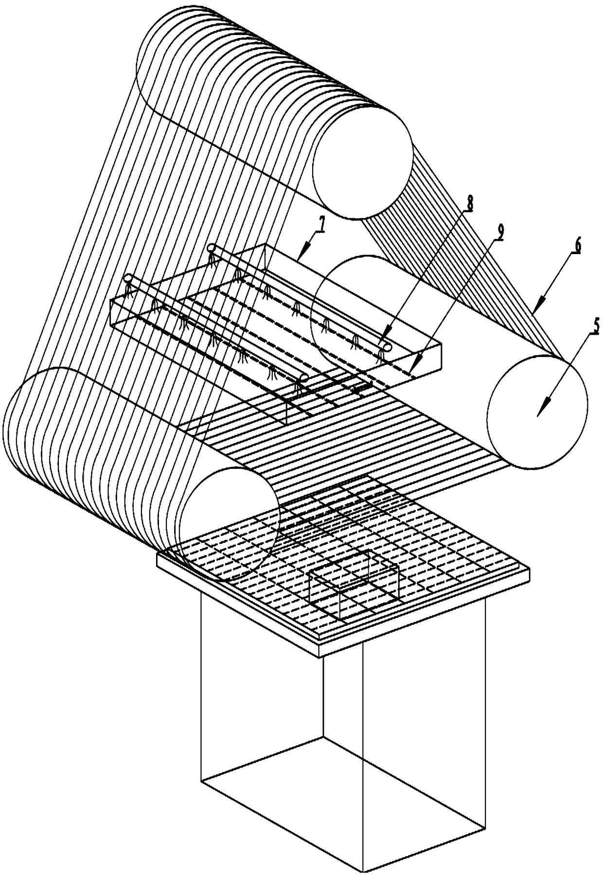
[0053] The multi-wire cutting machine consists of three sheaves on which several cutting wires arranged in parallel are wound, a working table located below the cutting lines, and a liquid leakage pipe located above the cutting lines.

[0054] Wherein, the surface of each sheave is coated with a polyurethane coating, and a plurality of V-shaped grooves with uniform groove spacing are opened on the polyurethane coating. It is also equipped with driving devices such as guide wheels, swing rods, take-up wheels, and pay-off wheels for the movement of the cutting line.

[0055] The worktable is driven by a screw rod and a servo device, and can move from bottom to top at a set speed.

[0056] The liquid suction pump provides power to make the mortar or coolant spray out from the leakage pipe, flow into the leakage box, and then evenly flow to the cutting line through the gap of the leakage box.

[0057] The units of dimensions described below are mm, the size of the multi-wire cutt...

Embodiment 2

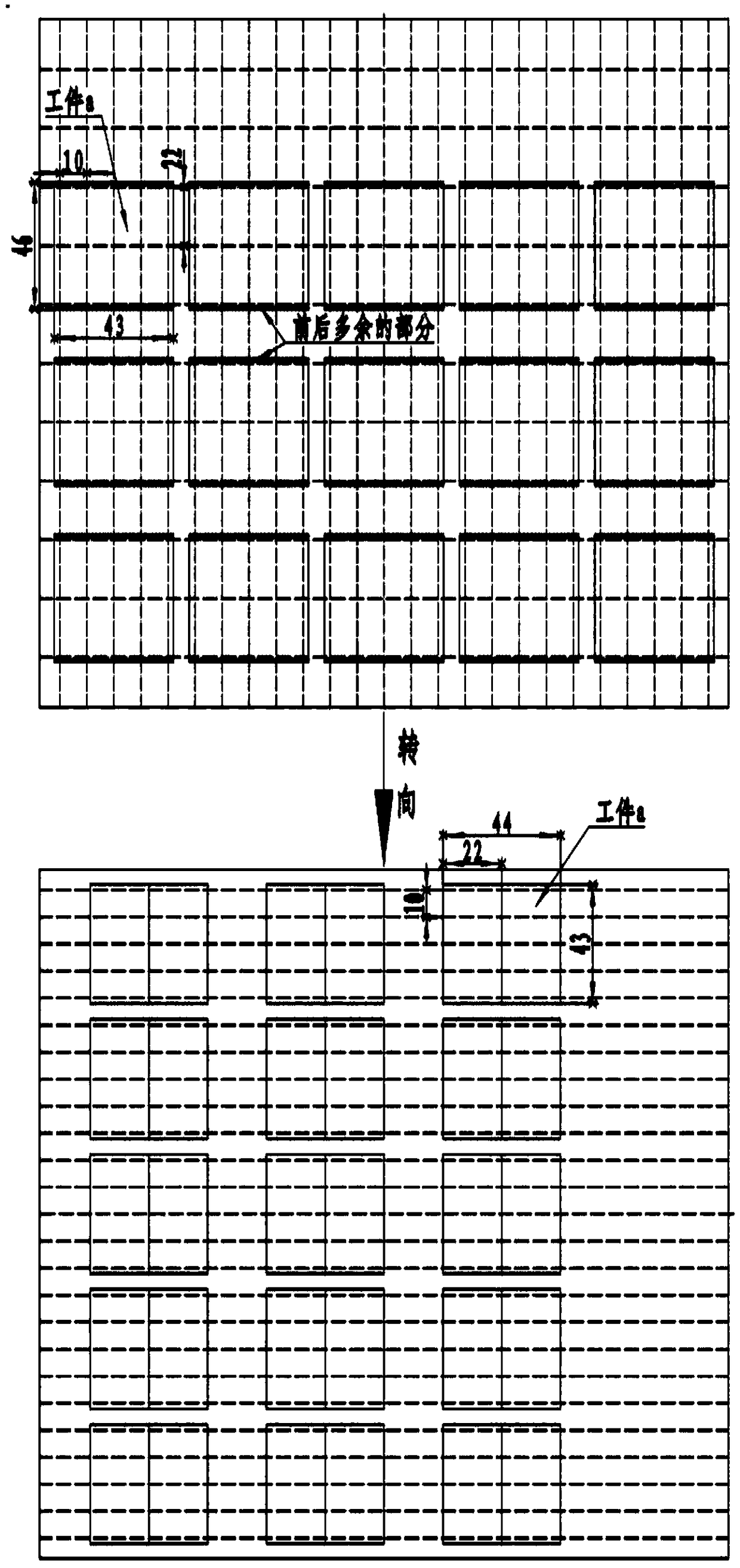
[0062] Embodiment 2 is basically the same as the multi-wire cutting method and multi-wire cutting machine of embodiment 1, and its difference is as Figure 4 As shown, the size of the two directions of the cut block is the same. The size of the block workpiece b is 46*46*38 as an example. After cutting, the corresponding size is 22*22*5. size.

[0063] In the above embodiment 2, only two multi-wire cutting machines are needed to complete the cutting in three directions.

[0064] The following table is the comparison of the processing time of each process of cutting 9 pieces of workpieces with a size of 46*46*38 into 252 pieces of 22*22*5 in Example 2. It can be seen that Example 2 can save about 24% of time:

[0065]

Embodiment 3

[0067] The multi-wire cutting method and the multi-wire cutting machine in embodiment 3 and embodiment 1 are basically the same, the difference is that the size of one direction of the square workpiece does not need to be cut, taking 46*43*15 as an example, the corresponding size after cutting For 22*10*15, only need to cut 22 and 10 direction size.

[0068] In the above embodiment 3, only two multi-wire cutting machines are needed to complete the cutting in two directions.

[0069] The following table is the comparison of the processing time of each process of cutting 15 pieces of workpieces with a size of 46*43*15 into 120 pieces of 22*10*15 in Example 3. It can be seen that Example 3 can save about 33% of time:

[0070]


PUM

PropertyMeasurementUnit
thicknessaaaaaaaaaa
diameteraaaaaaaaaa

Abstract

The invention discloses a multiple wire turning cutting method and equipment. The multiple wire turning cutting equipment is a multiple wire cutting machine and comprises a square multiple wire cutting base plate and a working table; two or more multiple wire cutting machines can be used for performing combined cutting. Compared with the conventional multiple wire cutting method and equipment, the multiple wire turning cutting method and equipment has the benefits that rapid cutting is realized, time spent on the intermediate auxiliary section is cut down, the material turnover time is reduced generally, cosmetic defects possibly caused during the material turnover process can be reduced, and the product quality is improved.

Description

technical field [0001] The invention belongs to the field of mechanical processing, and in particular relates to a method and equipment for steering multi-wire cutting. Background technique [0002] At present, the multi-wire cutting machine has been widely used in the processing of hard and brittle and precious materials such as optical glass, quartz crystal, semiconductor materials, special ceramics, sapphire, rare metals and alloys. It has the advantages of less material investment, less surface damage, low operating cost, and high processing efficiency. In the past two or three years, it has also been gradually implemented in the magnetic material processing industry. [0003] The initial blank of the magnetic material is generally a square, and the workpiece is processed by bonding together with 502 glue or other adhesives. It is: slice 1→remove glue and oil 1→grind 1→slice 2→remove glue and oil 2→grind 2→slice 3→remove glue and oil 3→grind 3. The process of removing ...

Claims


Application Information

Patent Timeline
Patent Type & Authority Patents(China)
IPC IPC(8): B28D5/04B28D7/00B28D7/02
CPCB28D5/042B28D7/00B28D7/02
Inventor 张泽清
Owner 京磁材料科技股份有限公司
Why Eureka
Try Eureka