Conjoined part injection mold

A technology for injection molds and parts, which is applied in the field of molds for integral injection molding of multiple parts, which can solve problems such as easy misalignment, low efficiency, and difficult assembly, and achieve the effect of ensuring consistency

Pending Publication Date: 2017-05-31
重庆腾增模具制造有限公司
View PDF2 Cites 0 Cited by
  • Summary
  • Abstract
  • Description
  • Claims
  • Application Information

AI Technical Summary

Problems solved by technology

[0002] At present, most plastic parts are single injection molded, although the molding effect is slightly better, but the efficiency is low, and because each part is independent of each other during molding, it is difficult to assemble after injection molding or the service life is short after assembly, easy to fall off, and the positional relationship with each other Not accurate enough, easy to misplace

Method used


Image

  • Conjoined part injection mold
  • Conjoined part injection mold
  • Conjoined part injection mold

Examples


Embodiment Construction

[0022] The implementation of the present invention will be illustrated by specific specific examples below, and those skilled in the art can easily understand other advantages and effects of the present invention from the contents disclosed in this specification.

[0023] Below in conjunction with accompanying drawing and embodiment the present invention will be further described:

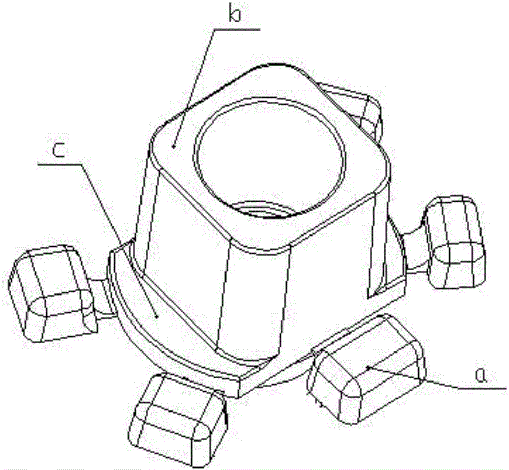
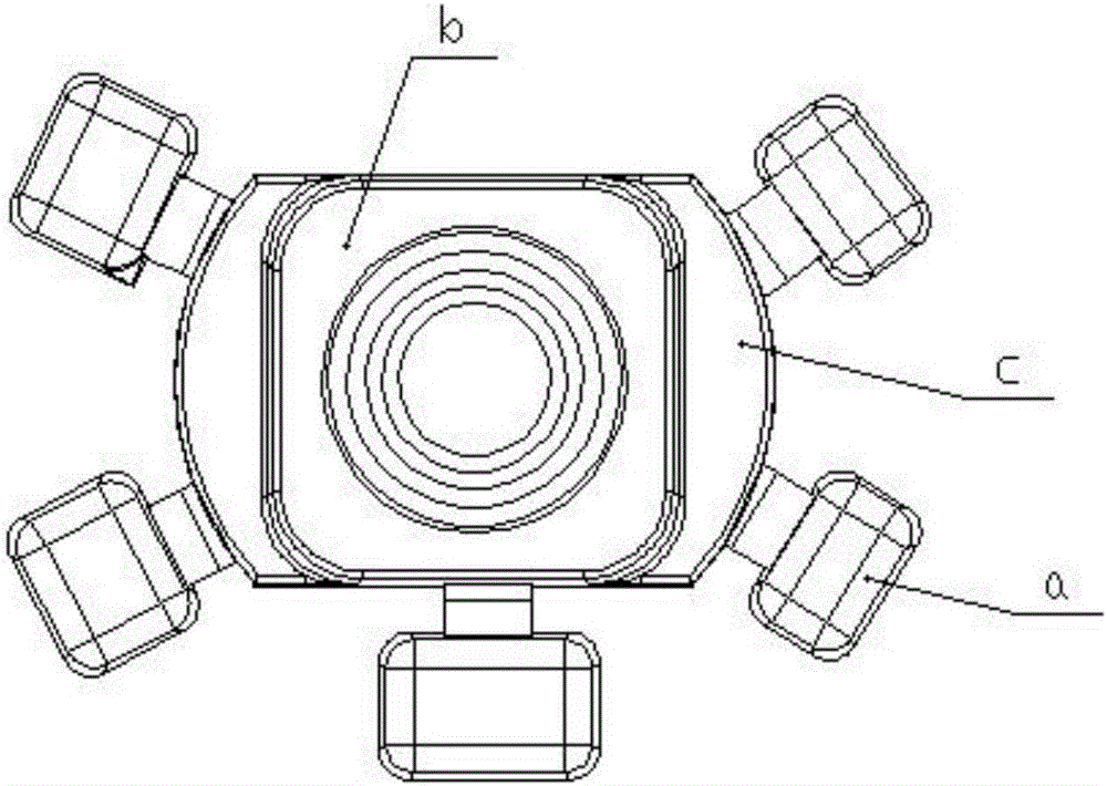
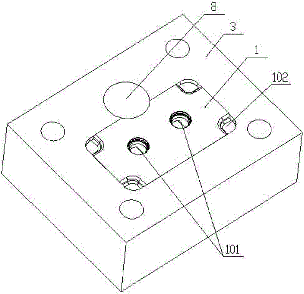
[0024] As shown in the figure, an injection mold for connected parts includes an upper mold 1 and a lower mold 2 for injection molding. The upper mold 1 is a rectangular parallelepiped structure with rounded corners, and the upper mold 1 is embedded in the upper mold base 3. The molding surface of the inner and upper mold 1 is flush with the mold embedded end face of the upper mold base, and the lower mold 2 is embedded in the lower mold base 4 .

[0025] Two circular blind holes 101 are arranged on the molding surface of the upper mold 1 along the center line of its length direction, and the two c...


PUM


Abstract

The invention discloses a conjoined part injection mold. The conjoined part injection mold comprises an upper mold body and a lower mold body which are used for injecting molding. The upper mold body is embedded into an upper mold base, and the forming face of the upper mold body is flush with the mold embedding end face of the upper mold base. The lower mold body is embedded into a lower mold base. The forming face of the upper mold body is provided with two circular blind holes, and the four corners of the upper mold body are provided with right-angle notches. The forming face of the lower mold body is provided with two stepped holes, and stepped shafts are fixed into the stepped holes. Rectangular grooves are formed in three sides of the open edge of each stepped hole, and the open ends of the rectangular grooves communicate with the open end of each stepped hole. A large circular through hole is formed between the upper mold body and the upper mold base. A cylindrical injection molding cap is arranged between the low mold body and the lower mold base and provided with a flow channel groove which communicates with a {-shaped pouring groove. The two ends of the pouring groove communicate with the open ends of the stepped holes. By adoption of the conjoined part injection mold, a plurality of parts can be integrally injection-molded and do not need to be combined and assembled again, the production efficiency is high, and the position precision of the parts at all positions is convenient to control.

Description

technical field [0001] The invention belongs to the technical field of injection molding, and in particular relates to a mold for integral injection molding of a plurality of parts. Background technique [0002] At present, most plastic parts are single injection molded, although the molding effect is slightly better, but the efficiency is low, and because each part is independent of each other during molding, it is difficult to assemble after injection molding or the service life is short after assembly, easy to fall off, and the positional relationship with each other Not accurate enough, easy to misplace. Such as figure 1 and 2 For the part shown in the figure, five rectangular blocks a and steps c need to be accurately surrounded and arranged in use, c is provided with a rectangular boss b, and the hollow circle of boss b connects with the center of the bottom of step c. During production, The rectangular block a, the step c, and the boss b of each part are formed sep...

Claims


Application Information

Patent Timeline
Patent Type & Authority Applications(China)
IPC IPC(8): B29C45/26B29C45/27
CPCB29C45/2602B29C45/2606B29C45/2701
Inventor 喻良冰
Owner 重庆腾增模具制造有限公司
Why Eureka
Try Eureka