Eureka AIR delivers breakthrough ideas for toughest innovation challenges, trusted by R&D personnel around the world.

An adjustable relay valve

A relay valve and sliding valve core technology, applied in the field of adjustable relay valve, can solve the problems of high and low temperature system damage and air leakage, reduction of vehicle brake air pressure, hidden danger of air brake system, etc., and achieve free control of brake sensitivity Effect

Active Publication Date: 2019-02-15
ZHEJIANG KELI VEHICLE CONTROL SYST
View PDF6 Cites 0 Cited by
  • Summary
  • Abstract
  • Description
  • Claims
  • Application Information

AI Technical Summary

Problems solved by technology

[0003] Due to the wear and tear of the brake parts and the influence of the surrounding environment during the driving of medium and heavy trucks and large buses equipped with air brake systems, it is inevitable that water accumulation in the low temperature system pipes will freeze and blockage, and water accumulation in system components will inevitably occur. Faults such as freezing card, high and low temperature system damage and air leakage can easily cause the vehicle brake pressure to drop, resulting in major traffic safety accidents. Therefore, the existing air pressure brake system has a large safety hazard

Method used


Image

  • An adjustable relay valve
  • An adjustable relay valve
  • An adjustable relay valve

Examples


Embodiment 1

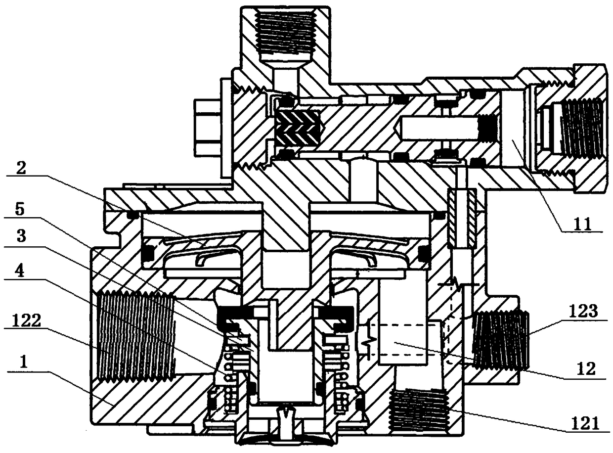
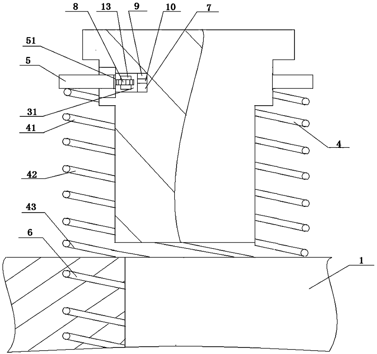
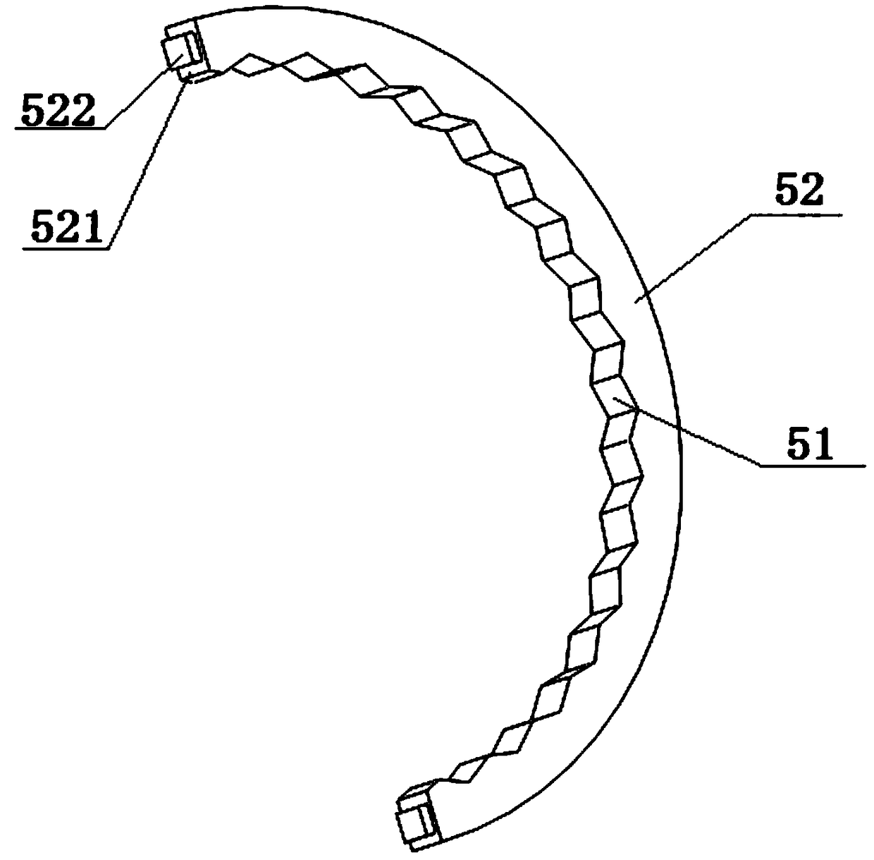
[0023] An adjustable relay valve, comprising a valve body 1, a piston 2 is installed in the valve body 1, and the inside of the valve body 1 is divided into an upper air chamber 11 and a lower air chamber 12 by the piston 2, and a piston located in the valve body 1 is installed in the valve body 1. 2 The sliding spool 3 pushed by the piston 2 below, the lower air chamber 12 is provided with an exhaust hole 121, a first port 122 connected with the air reservoir and a second port 123 connected with the brake chamber, the sliding spool 3 The up and down displacement controls the connection between the exhaust hole 121, the first port 122 and the second port 123. An annular installation groove 31 is arranged on the outer surface of the sliding valve core 3, and a control cavity is arranged in the installation groove 31. Inside the control cavity A controller 7 and a gear 8 controlled by the controller 7 to rotate are installed. An annular rotating piece 5 that rotates around the ax...


PUM


Abstract

The invention relates to a relay valve and discloses an adjustable relay valve comprising a valve body (1). A piston (2) is mounted in the valve body (1). An annular mounting groove (31) is formed in a sliding valve element (3). An annular rotating piece (5) is mounted in the mounting groove (31). The adjustable relay valve further comprises a return spring (4). The upper end of the return spring (4) is fixed to the annular rotating piece (5). A spiral groove (6) is formed in the lower portion of the valve body (1). A controller (7) controls the depth of screwing in the spiral groove (6) of the return spring (4). The annular rotating piece drives the return spring to rotate, by combining the spiral groove, the return spring can be screwed in the spiral groove in the rotating process, accordingly the function of control over the effective length of the return spring is achieved, and the effect that the braking sensitivity is controlled freely through the adjustable return spring is achieved.

Description

technical field [0001] The invention relates to a relay valve, in particular to an adjustable relay valve. Background technique [0002] The safety of automobile driving is closely related to the reliability of the braking system. The pneumatic brake system has been widely used in medium and heavy trucks and large passenger cars because of its high reliability, fast response, low manufacturing cost, and no pollution. Existing air pressure brake system is mainly provided with two sets of independent braking devices, i.e. parking brake device and service brake device. When braking, the driver controls the dual-chamber brake master valve through the pedal, and the high-pressure gas in the high-pressure air storage tank is sent to the brake cylinders of the front and rear axles of the vehicle through the dual-chamber brake master valve. Push the brake cylinders to work, and the push rods of each brake cylinder stretch out to drive the brake drums to realize service braking. W...

Claims


Application Information

Patent Timeline
Patent Type & Authority Patents(China)
IPC IPC(8): B60T15/18
CPCB60T15/18
Inventor 马靖
Owner ZHEJIANG KELI VEHICLE CONTROL SYST
Why Eureka
Eureka Blog
Learn More