Zero (micro) gravity suspension method and device with zero-frequency vibration isolation characteristic
A suspension device and microgravity technology, which is applied in the simulation device of space navigation conditions, transportation and packaging, space navigation equipment, etc. question
- Summary
- Abstract
- Description
- Claims
- Application Information
AI Technical Summary
Problems solved by technology
Method used
Image
Examples
specific Embodiment approach 1
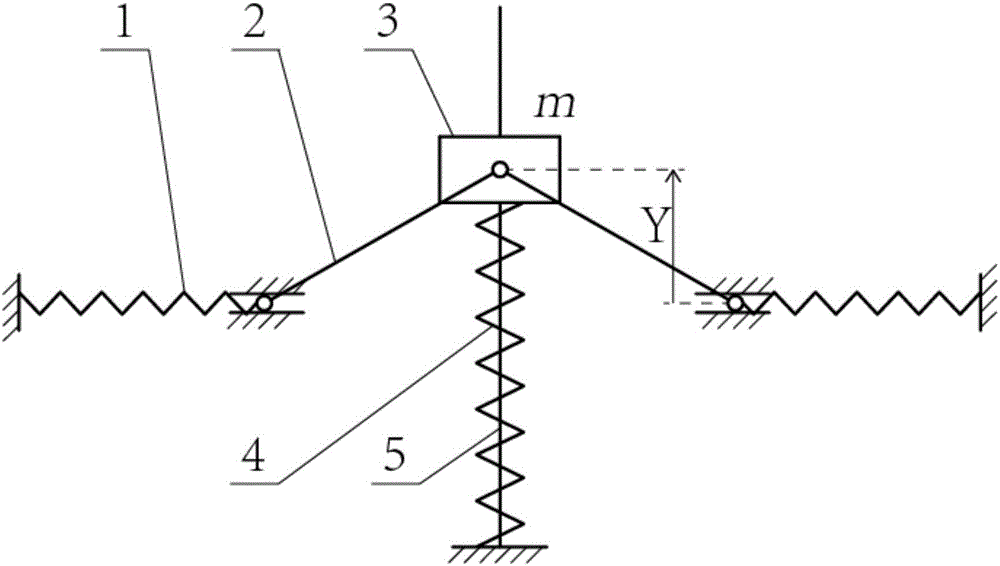
[0075] Specific implementation mode one: as figure 1 As shown, the suspension device described in this embodiment is a spring-connecting rod-rail mechanism zero (micro) gravity suspension device,
[0076] The suspension device comprises two horizontal extension springs 1, two connecting rods 2, an intermediate mass 3, a vertical spring 4 and a vertical polished rod 5, the intermediate mass 3 is fixedly connected to the upper end of the vertical spring 4, and the intermediate mass 3 slide up and down along the vertical polished rod 5 under the action of the connecting rods 2 on both sides; one end of each connecting rod 2 is hinged to one end of the horizontal tension spring 1, and the other end of each connecting rod 2 is hinged to the intermediate mass 3;
[0077] The one end of each horizontal extension spring 1 can move along the horizontal guide rail of corresponding end, and the other end of horizontal extension spring 1 is fixed; The lower end of vertical spring 4 is fix...
specific Embodiment approach 2
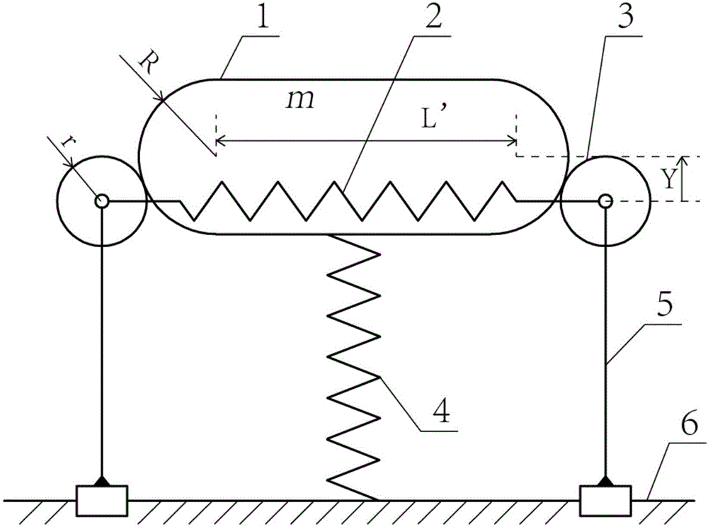
[0085] Specific implementation mode two: as figure 2 As shown, the levitation device described in this embodiment is a spring-roller-rail mechanism zero (micro) gravity levitation device,
[0086] The suspension device includes an intermediate mass 1, a horizontal tension spring 2, two rollers 3, a vertical spring 4, two supports 5 and a guide rail 6,
[0087] The intermediate mass 1 is fixedly connected to the upper end of the vertical spring 4, and moves in the vertical direction under the action of the rollers 3 on both sides of the intermediate mass 1; each roller 3 is hinged on the upper end of a corresponding support 5, and the support 5 The lower end of the guide rail 6 constitutes a sliding pair,
[0088] The centers of the two rollers 3 are connected by a horizontal tension spring 2, and the bracket 5 can slide left and right along the guide rail 6 in the horizontal direction so as to change the distance between the two rollers 3;
[0089] The mass of the intermedi...
specific Embodiment approach 3
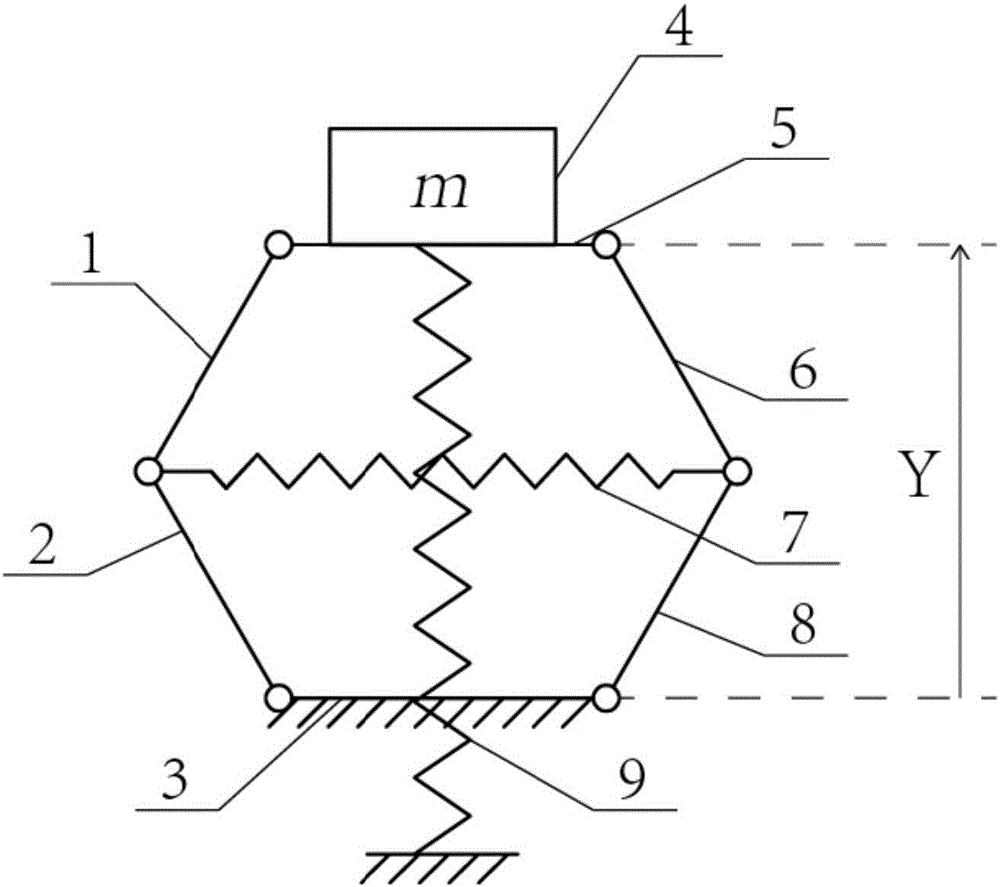
[0095] Specific implementation mode three: as image 3 As shown, the suspension device described in this embodiment is a spring-six-bar linkage mechanism zero (micro) gravity suspension device,
[0096] The suspension device includes a first connecting rod 1, a second connecting rod 2, a third connecting rod 3, a fourth connecting rod 8, a fifth connecting rod 6, a sixth connecting rod 5, an intermediate mass 4, and a horizontal tension spring 7 and vertical spring 9,
[0097] The first connecting rod 1, the second connecting rod 2, the third connecting rod 3, the fourth connecting rod 8, the fifth connecting rod 6, and the sixth connecting rod 5 are sequentially hinged to form a hexagon, and the sixth connecting rod 5 is located at the The top of the three connecting rods 3 and both of them are arranged horizontally, the third connecting rod 3 is fixedly arranged, and the intermediate mass block 4 is fixedly connected with the sixth connecting rod 5;
[0098] One end of the...
PUM
 Abstract
Description
Claims
Application Information
 - R&D
- Intellectual Property
- Life Sciences
- Materials
- Tech Scout
- Unparalleled Data Quality
- Higher Quality Content
- 60% Fewer Hallucinations
Browse by: Latest US Patents, China's latest patents, Technical Efficacy Thesaurus, Application Domain, Technology Topic, Popular Technical Reports.
© 2025 PatSnap. All rights reserved.Legal|Privacy policy|Modern Slavery Act Transparency Statement|Sitemap|About US| Contact US: help@patsnap.com


