
Full-automatic box changing machine

A fully automatic, box machine technology, used in conveyors, conveyor objects, transportation and packaging, etc., can solve problems such as reducing production efficiency and increasing labor force

Inactive Publication Date: 2017-05-31
温岭市正凯自动化设备有限公司
View PDF7 Cites 4 Cited by
  • Summary
  • Abstract
  • Description
  • Claims
  • Application Information

AI Technical Summary

Problems solved by technology

However, these production line enterprises need to manually transport the products processed in the production workshop to the conveying mechanism before they can be transported to the next workshop for subsequent processes. This process will greatly increase the labor force and greatly reduce the production efficiency. , which cannot meet the needs of production line enterprises

Method used


Image

  • Full-automatic box changing machine
  • Full-automatic box changing machine
  • Full-automatic box changing machine

Examples


Embodiment 1

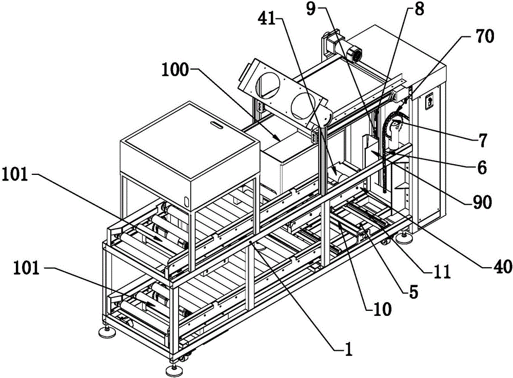
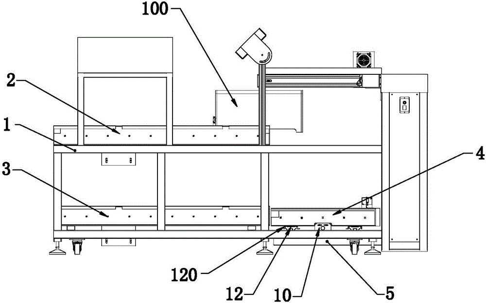
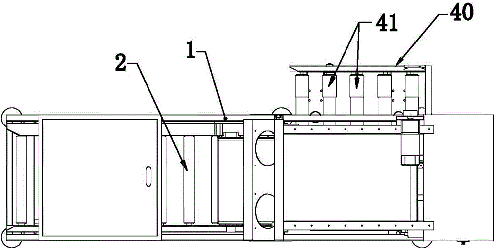
[0032] Such as figure 1 — image 3 As shown, the present invention discloses a fully automatic case changing machine. In a specific embodiment of the present invention, it includes a frame 1, and the frame 1 is provided with two layers of upper conveying components 2 and lower conveying components with opposite conveying directions. Assemblies 3, the frame 1 is provided with a case carrying assembly 4 for transporting the case 100 on the upper conveying assembly 2 to the lower conveying assembly 3, the bottom of the carrying case assembly 4 is provided with a bottom plate 5, and the frame 1 A longitudinal conveying assembly for driving the bottom plate 5 to move longitudinally is arranged on it.

[0033] In a specific embodiment of the present invention, a lateral conveying assembly for driving the container assembly 4 to move laterally is arranged between the container assembly 4 and the bottom plate 5 .

[0034] By adopting the above-mentioned technical scheme, it is not n...

Embodiment 2

[0051] Such as Figure 4 — Figure 7 As shown, the present invention discloses a fully automatic case changing machine. In a specific embodiment of the present invention, it includes a frame 110, and the frame 110 is provided with two layers of upper conveying assemblies 200 and lower conveying assemblies with opposite conveying directions. Assemblies 300, the frame 110 is provided with a case carrying assembly 400 for transporting the boxes on the upper conveying assembly 200 to the lower conveying assembly 300, the bottom of the carrying case assembly 400 is provided with a bottom plate 500, on the frame 110 A longitudinal conveying assembly for driving the bottom plate 500 to move longitudinally is provided.

[0052] By adopting the above-mentioned technical scheme, it is not necessary to manually transport the produced products to the conveying mechanism, and the products can be transported to the next workshop for subsequent processes, which reduces manual labor, improve...


PUM


Abstract

The invention relates to the technical field of mechanical equipment, in particular to a full-automatic box changing machine for a production line. The technical scheme is achieved in the manner that the full-automatic box changing machine is characterized by comprising a rack, the rack is provided with two layers of conveying assemblies including an upper conveying assembly and a lower conveying assembly which are opposite in conveying direction, and the rack is provided with a box carrying assembly used for conveying boxes on the upper conveying assembly to the lower conveying assembly; and a bottom plate is arranged at the bottom of the box carrying assembly, and the rack is provided with a longitudinal conveying assembly used for driving the longitudinal movement of the bottom plate. The full-automatic box changing machine has the beneficial effects that products can be conveyed to a next workshop to be subjected to the subsequent procedure without manual carrying of the produced products to a conveying mechanism, the manual work labor force is reduced, the production efficiency is improved, automation is achieved, and accordingly the requirements of production line enterprises are met. The full-automatic box changing machine is high in practicability and easy to popularize.

Description

technical field [0001] The invention relates to the technical field of mechanical equipment, in particular to a fully automatic case changing machine used in a production line. Background technique [0002] At present, in order to realize automatic production in most production enterprises in China, most enterprises often transport the finished products to the next workshop through the conveying mechanism in the production workshop for subsequent processes, such as some production workshops with multiple CNC machining lathes and other production equipment . However, these production line enterprises need to manually transport the products processed in the production workshop to the conveying mechanism before they can be transported to the next workshop for subsequent processes. This process will greatly increase the labor force and greatly reduce the production efficiency. , so as not to meet the needs of production line enterprises. [0003] Therefore, in view of the abov...

Claims


Application Information

Patent Timeline
Patent Type & Authority Applications(China)
IPC IPC(8): B65G47/54B65G47/24
CPCB65G47/24B65G47/54B65G2201/025
Inventor 程良照
Owner 温岭市正凯自动化设备有限公司
Learn More