Automatic belt cutting machine

A tape cutting machine, automatic technology, applied in the direction of winding strips, sending objects, thin material processing, etc., can solve the problems of slow cutting action, occupying a large space, and low cutting efficiency, etc., and achieves fast cutting action. Wide application range and high cutting efficiency

Active Publication Date: 2017-05-31
福建锦特新材料科技有限公司
View PDF12 Cites 2 Cited by
  • Summary
  • Abstract
  • Description
  • Claims
  • Application Information

AI Technical Summary

Problems solved by technology

[0002] Chinese invention patent (publication number CN101643996) discloses an automatic tape cutting machine. The tape cutting platform needs to be set longer and takes up a lot of space; the feeding side of the knife rest on the tape cutting platform only passes through a horizontal axis. And on the horizontal axis, vertical positioning plates are installed at intervals to position both sides of the ribbon to prevent the ribbon from moving. However, when the ribbon passes under the horizontal axis, the horizontal axis does not generate tension on the ribbon. There are often problems of slack and insufficient tension before feeding into the feed roller, which will affect the normal feeding of the feed roller and the cutting accuracy of the cutter; at the same time, the feed roller is driven by a stepping motor and fixed on the cutter On the belt platform, the distance between the roller surface of the feed roller and the belt cutting platform cannot be adjusted according to the thickness of the ribbon to be cut, and the scope of application has certain limitations; Straight up and down to complete the lifting and cutting action, the cutting action is relatively slow and the cutting efficiency is relatively low

Method used


Image

  • Automatic belt cutting machine
  • Automatic belt cutting machine
  • Automatic belt cutting machine

Examples


Embodiment Construction

[0022] In the following, the present invention will be further described in conjunction with the accompanying drawings and specific embodiments, so as to understand more clearly the technical idea claimed in the present invention.

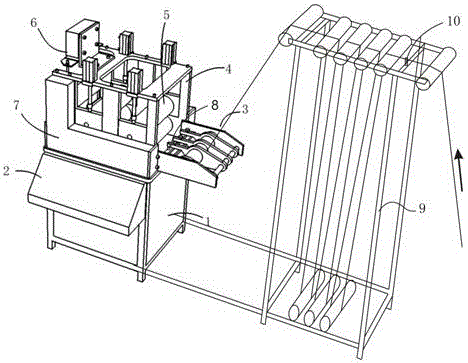
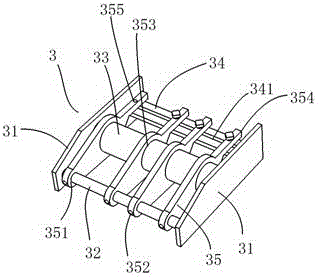
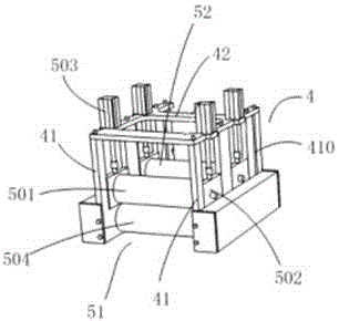
[0023] Such as Figure 1-4 An automatic tape cutting machine of the present invention is shown, comprising a distribution box 1, a console 2, a positioning anti-channeling frame 3, a feed roller frame 4, a feed roller device 5, a cutter device 6 and a transmission box 7, and the console 2 is set On the side of the distribution box 1, the feeding roller frame 4 is installed on the upper end of the distribution box 1, the positioning anti-channeling frame 3 is installed and fixed on the feeding end of the feeding roller frame 4, and the feeding roller device 5 is installed on the feeding roller frame 4 Above, the cutter device 6 is installed on the discharge end of the feed roller frame 4, and the transmission box 7 is installed on the outer wall of ...


PUM


Abstract

The invention discloses an automatic belt cutting machine which comprises a power distribution box, a control console, a positioning migration preventing frame, a feeding roller rack, feeding roller devices, a cutter device and a transmission box. The positioning migration preventing frame is mounted and fixed at a feeding end of the feeding roller frame and comprises a shaft fixing side plate, a fastening shaft, a tensioning shaft, a fastening transverse plate and a positioning plate, the feeding roller devices are mounted on the feeding roller frame and include a first feeding roller device and a second feeding roller device, upper pressing rollers of the first feeding roller device and the second feeding roller device are liftable and adjustable, the cutter device is mounted at a discharging end of the feeding roller frame, and an upper cutter of the cutter device is directly driven by a cutter lifting cylinder to go up and down for cutting. The automatic belt cutting machine has the advantages of compact structure, small occupied space, freeness of loosening during woven belt conveying, wide application range, high cutting efficiency, high accuracy and capability of automatically detecting broken weft and cutting off woven belt sections with the broken weft.

Description

technical field [0001] The invention relates to the technical field of ribbon cutting, in particular to an automatic ribbon cutting machine. Background technique [0002] Chinese invention patent (publication number CN101643996) discloses an automatic tape cutting machine. The tape cutting platform needs to be set longer and takes up a lot of space; the feeding side of the tool holder on the tape cutting platform only passes through a horizontal axis. And on the horizontal axis, vertical positioning plates are installed at intervals to position the two sides of the ribbon to prevent the ribbon from moving. However, when the ribbon passes under the horizontal axis, the horizontal axis does not generate tension on the ribbon. There are often problems of slack and insufficient tension before feeding into the feed roller, which will affect the normal feeding of the feed roller and the cutting accuracy of the cutter; at the same time, the feed roller is driven by a stepping motor...

Claims


Application Information

Patent Timeline
Patent Type & Authority Applications(China)
IPC IPC(8): B65H35/02B65H20/30B65H23/26
CPCB65H20/30B65H23/26B65H35/02
Inventor 尤金体苗灵芳尤小明李美丽
Owner 福建锦特新材料科技有限公司
Why Eureka
Try Eureka