Supercharge Your Innovation With Domain-Expert AI Agents!

Regenerator in catalytic cracking device

A catalytic cracking device and regenerator technology, applied in catalytic cracking, cracking, petroleum industry, etc., can solve the problem that ammonia and other compounds cannot be effectively processed

Active Publication Date: 2017-05-31
PETROCHINA CO LTD
View PDF5 Cites 0 Cited by
  • Summary
  • Abstract
  • Description
  • Claims
  • Application Information

AI Technical Summary

Problems solved by technology

[0005] The present invention solves the problems of CO and NO in the catalyst burning process in the prior art by adjusting the quantity and position of the catalyst delivery pipeline and the main air pipeline. X Revert to N 2 The reaction can not be effectively carried out or incompletely regenerated. High levels of ammonia and other compounds in the flue gas lead to NO in the final exhaust flue gas. X high problem

Method used


Image

  • Regenerator in catalytic cracking device
  • Regenerator in catalytic cracking device
  • Regenerator in catalytic cracking device

Examples


Embodiment 1

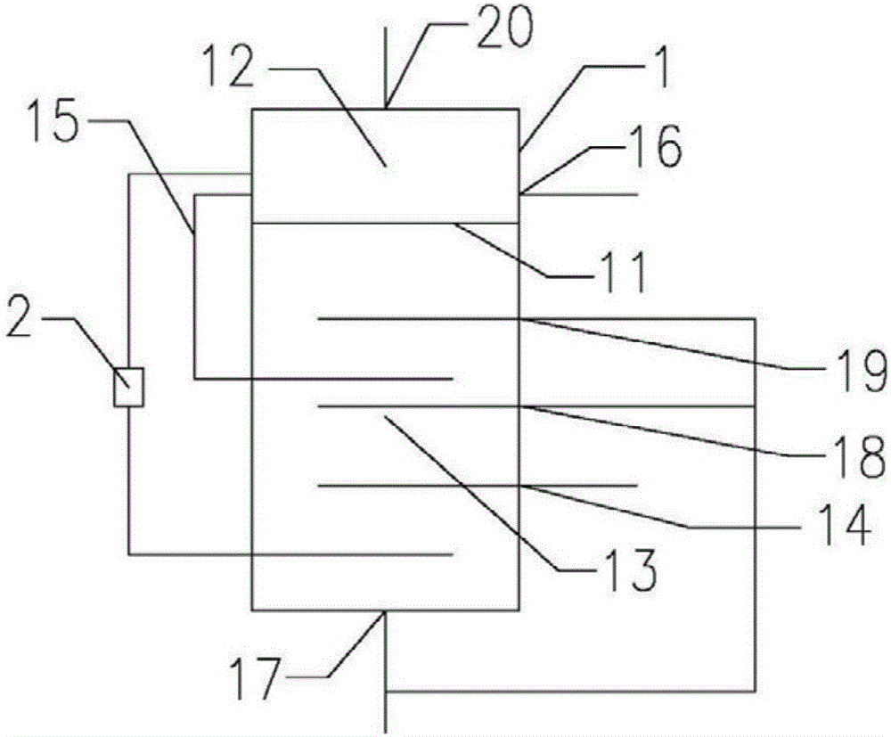
[0025] A regenerator in a catalytic cracking unit, the regenerator 1 includes a large hole distribution plate 11, a catalyst inlet 14, a catalyst circulation pipeline 15, a regenerated catalyst outlet 16, a main air pipeline I17, a main air pipeline II18, a main air Pipeline III19, flue gas outlet 20;

[0026] The large hole distribution plate 11 in the regenerator 1 divides the regenerator 1 into an upper two-dense bed 12 and a lower charred pot 13, and the inlet 14 of the catalyst to be produced is arranged on the side of the charred pot 13, and the The main air pipeline I17 is arranged at the bottom of the coking tank 13, the main air pipeline II18 and the main air pipeline III19 are arranged on the side of the coking tank 13, the inlet of the catalyst circulation pipeline 15 and the inlet of the external heat collector 2 are arranged On the side of the double-dense bed 12, the outlet of the catalyst circulation line 15 and the outlet of the external heat collector 2 are ar...

Embodiment 2

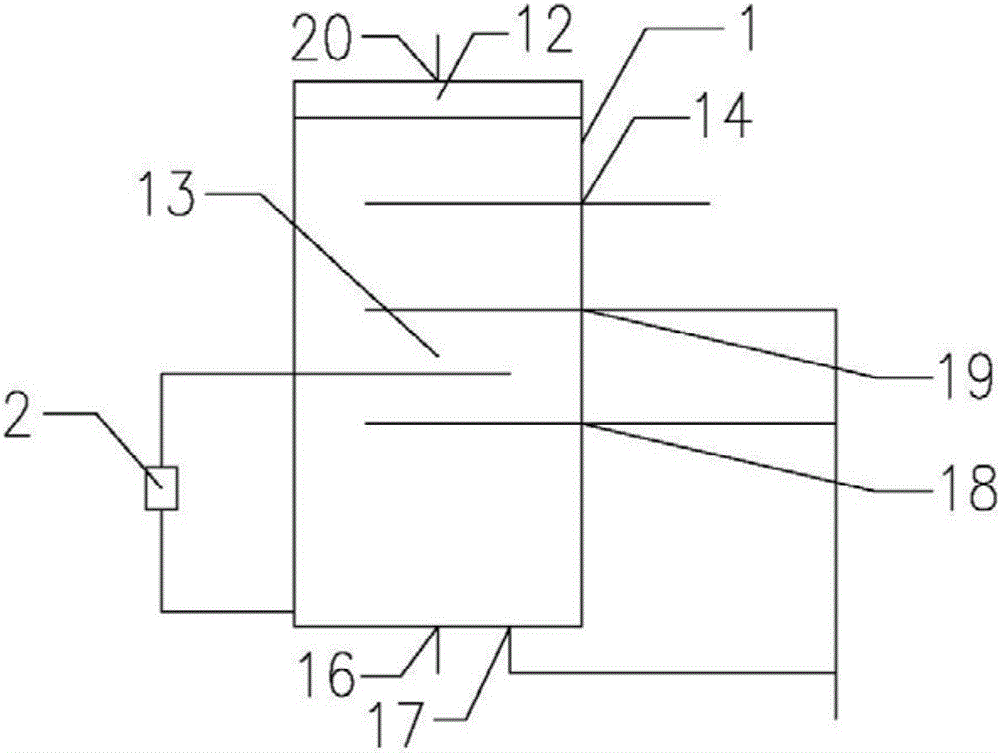
[0035] A regenerator in a catalytic cracking unit, the regenerator 1 includes a standby catalyst inlet 14, a regenerated catalyst outlet 16, a main air pipeline I17, a main air pipeline II18, a main air pipeline III19, and a flue gas outlet 20;

[0036] The upper part of the regenerator 1 is a dilute-phase space 12, and the lower part is a dense-phase catalyst bed 13. The inlet 14 of the standby catalyst is arranged on the side of the dense-phase catalyst bed 13, and the main air line I17 is arranged on the dense-phase catalyst bed. 13, the main air pipeline II18 and the main air pipeline III19 are arranged on the side of the catalyst dense-phase bed 13, and the inlet of the external heat extractor 2 and the outlet of the external heat extractor 2 are arranged on the side of the catalyst dense-phase bed 13. Side, the distance from the standby catalyst inlet 14 to the bottom of the catalyst dense-phase bed 13>the distance from the main air line III19 to the bottom of the catalys...


PUM


Abstract

The invention relates to a regenerator in a catalytic cracking device, and belongs to the field of petroleum processing. The regenerator comprises a plurality of catalyst delivery pipelines and a plurality of main air pipelines, wherein the plurality of catalyst delivery pipelines are arranged at different heights of the same bed of the regenerator; and the plurality of main air pipelines are arranged at different heights of the same bed of the regenerator. The regenerator provided by the invention can reduce the NOX content in fume by 55-70%.

Description

technical field [0001] The invention relates to a regenerator in a catalytic cracking device, belonging to the field of petroleum processing. Background technique [0002] Catalytic cracking is an important secondary processing technology in petroleum processing, and catalytic cracking unit is usually the core unit of refinery. The catalytic cracking unit includes reactors, regenerators and external heat extractors. The raw oil enters the reactor and is converted into liquefied gas, gasoline and diesel under the action of a certain temperature, pressure and catalyst. The catalyst loses its activity due to the deposition of coke during the reaction. The regenerator is used to burn the deactivated catalyst with the main air at a certain temperature and pressure to burn off the coke, so that the catalyst is reactivated and then sent back to the reactor. The flue gas produced by the coke is finally discharged into the atmosphere after energy recovery. During the burning proces...

Claims


Application Information

Patent Timeline
Patent Type & Authority Applications(China)
IPC IPC(8): C10G11/14
CPCC10G11/14
Inventor 吴宇李炜祁兴国董森
Owner PETROCHINA CO LTD
Features
  • R&D
  • Intellectual Property
  • Life Sciences
  • Materials
  • Tech Scout
  • Unparalleled Data Quality
  • Higher Quality Content
  • 60% Fewer Hallucinations
Learn More