
Automatic button sewing machine

A button sewing machine, sewing machine technology, applied in sewing machine components, sewing equipment, textiles and papermaking, etc., can solve the problems of increasing burden and manufacturing costs, unable to configure multiple button feed slots at the same time, and low button button efficiency, etc. The effect of reducing cost burden, improving buttoning efficiency and reducing site occupation

Inactive Publication Date: 2017-05-31
广西风华服饰有限责任公司
View PDF7 Cites 4 Cited by
  • Summary
  • Abstract
  • Description
  • Claims
  • Application Information

AI Technical Summary

Problems solved by technology

Due to space constraints, it is not possible to configure multiple button feeding slots on an automatic button sewing machine at the same time. Therefore, the single-diameter button feeding mode of the existing automatic button sewing machine determines that multiple buttons are required to button a shirt. The automatic button sewing machine is completed by the cooperation of multiple operators: one operator operates an automatic button sewing machine to sew buttons of a certain diameter, and then hands over to the next operator to operate another automatic button sewing machine to sew Sew buttons of the second disc diameter, and so on until all buttons of the disc diameter are nailed and sewn
[0008] This button feeding method not only needs to occupy a large number of automatic button sewing machines and operators, but also increases the burden on the enterprise and the manufacturing cost, and a piece of clothing needs to pass through different automatic button buttons in the process of completing all button buttons. The multiple transfer process between sewing machines has many unnecessary transfer processes, resulting in low efficiency of buttoning, and the material is prone to errors during the transfer process

Method used


Image

  • Automatic button sewing machine
  • Automatic button sewing machine

Examples


Embodiment Construction

[0017] The present invention will be further described below in conjunction with the accompanying drawings and specific embodiments.

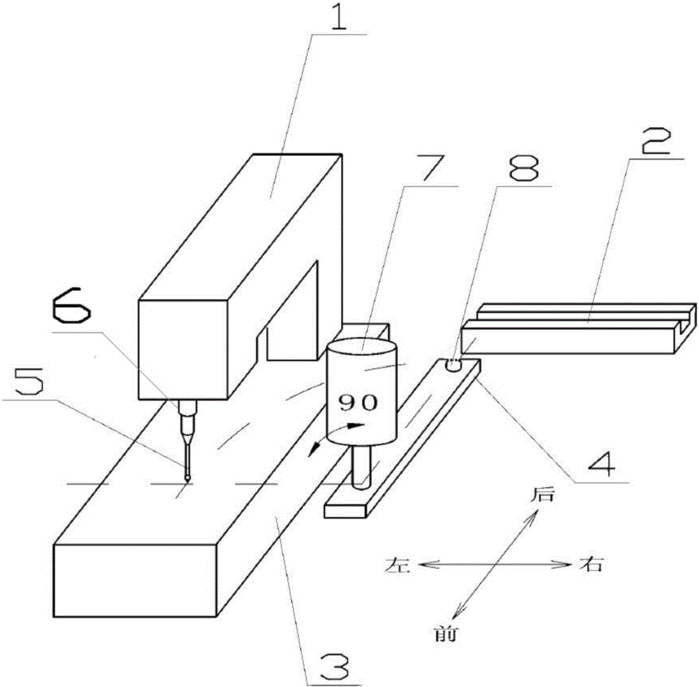
[0018] Reference attached figure 1 , The automatic button sewing machine includes a sewing head 1, a button sending rotary plate 4, a sewing machine base 3 and a button sending groove 2.

[0019] The sewing machine head 1 is in the shape of a right angle "7" vertically arranged front and rear, its rear end is a vertical end, fixedly installed on the sewing machine base 3 table, the front end is a cantilever end, and the bottom of the cantilever end is installed with a sewing needle 5 that can be vertically lifted up and down. , There is a space between the sewing needle 5 and the sewing machine base 3 tabletops below it.

[0020] A horizontal buckle-feeding rotating plate 4 is arranged on the right side of the sewing machine head 1. The height of the buckle-feeding rotating plate 4 is located between the sewing machine base 3 table and the sew...


PUM


Abstract

The invention provides an automatic button sewing machine which comprises a sewing machine head, a button supplying rotary plate, a sewing machine seat and a button supplying groove. When in an initial position, the button supplying rotary plate is parallel to the sewing machine head, the discharge end of the button supplying groove is connected with button positioning grooves of the button supplying rotary plate separately, buttons fall into the button positioning grooves from a hole formed in the bottom of the button supplying groove, and the position is a button mounting position; and the button supplying rotary plate horizontally rotates by 90 degrees anticlockwise from the button mounting position, the button positioning grooves of the button supplying rotary plate are arranged just below a sewing needle, and the position is a button sewing position. A plurality of button positioning grooves each is in a circular shape and share a center point, and the smaller the size is, the deeper the button positioning groove is; and a negative adsorption device is arranged on the sewing machine head and is used for sucking up the buttons delivered by the button supplying rotary plate and enabling the buttons to suspend so as to enable the button supplying rotary plate to leave and lappet to cover the position. One automatic button sewing machine can be utilized to sew the buttons with various disc diameters on clothing, and the button sewing efficiency is greatly improved.

Description

technical field [0001] The invention belongs to the technical field of garment processing machinery, in particular to an automatic button sewing machine. Background technique [0002] The automatic button sewing machine is a special automatic sewing machine, which completes the sewing of buttons with regular shapes, and the most commonly used ones are the sewing of buttons with disc-shaped two-hole or four-hole (also known as flat buttons). [0003] A common automatic button sewing machine usually includes a sewing machine head, a button claw, a button feeding rotary plate and a sewing machine seat. The sewing machine head is in the shape of a right angle "7" vertically arranged front and rear, its rear end is a vertical end, fixedly installed on the sewing machine table, the front end is a cantilever end, and the bottom of the cantilever end is equipped with sewing needles that can be lifted vertically up and down. There is a space between it and the sewing machine seat ta...

Claims


Application Information

Patent Timeline
Patent Type & Authority Applications(China)
IPC IPC(8): D05B3/14D05B3/22D05B33/00
CPCD05B3/14D05B3/22D05B33/00
Inventor 邱柳新
Owner 广西风华服饰有限责任公司
Learn More