A water conservancy water retaining gate power generation device

A technology of power generation device and water gate, which is applied in water supply devices, wind energy power generation, water conservancy projects, etc., can solve the problems of deformation of the water retaining gate, reduce the fatigue strength of the water retaining gate, water leakage, etc., and achieve the effect of avoiding impact.

Active Publication Date: 2018-11-16
华睿(无锡)知识产权运营有限公司
View PDF8 Cites 0 Cited by
  • Summary
  • Abstract
  • Description
  • Claims
  • Application Information

AI Technical Summary

Problems solved by technology

[0003] In many large and small water conservancy projects in China, the water retaining gate is a kind of component that must be installed. Through the opening and closing of the water retaining gate, the operation of water storage and flood discharge is realized. The current retaining gate is only this kind Because the water retaining gate bears high pressure on one side all the year round, it is easy to cause deformation of the water retaining gate and affect the side seal, resulting in water leakage
And when the sluice gate is raised (especially sometimes when a small amount of water needs to be released, half of the sluice gate needs to be raised), the shear stress of the lower flowing water on the lower end of the sluice gate is very concentrated, which easily causes the lower side of the sluice gate to the bend
[0004] Due to the eddy effect of water, a lot of floating objects will be concentrated on the side of the water retaining gate all the year round. The floating objects not only pollute the water quality and affect the landscape, but also repeatedly impact the water retaining gate with the impact of the water flow, reducing the water retaining gate fatigue strength
The existing method is manual fishing, but this operation not only consumes a lot of manpower, but also causes production accidents

Method used


Image

  • A water conservancy water retaining gate power generation device
  • A water conservancy water retaining gate power generation device
  • A water conservancy water retaining gate power generation device

Examples


Embodiment 1

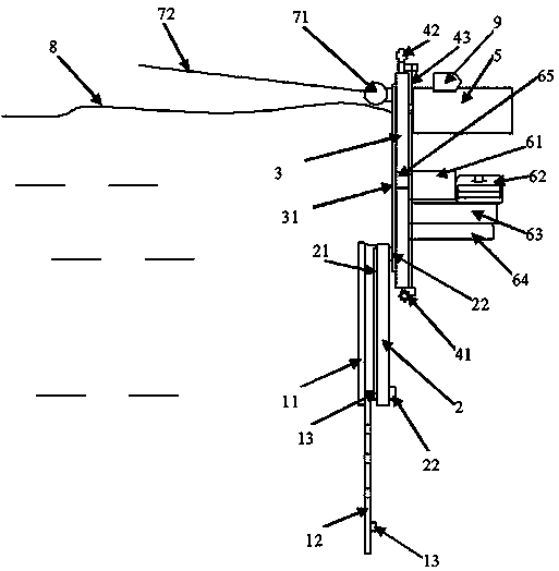
[0034] A power generation device for a water retaining gate, comprising a first gate, a second gate, a third gate, an impeller device, a generator set, a sewage treatment device, a control device and a floating matter collection device.

[0035] The first gate includes an outer plate and an inner plate, the outer plate can slide upward along the inner plate, the inner plate is porous, and the inner plate of the first gate is provided with a first slider, so One side of the second gate is provided with a first slide rail to cooperate with the first slide block, the other side of the second gate is provided with a second slide block, and one side of the third gate is provided with a second slide rail. The rail is matched with the second slider, the generator set is arranged on the upper part of the other side of the third gate, and the sewage treatment device is arranged on the lower part.

[0036] The height of the third gate is greater than that of the first gate and also grea...

Embodiment 2

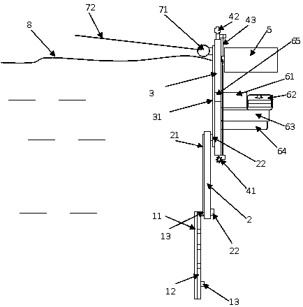
[0051] A power generation device for a water retaining gate, comprising a first gate, a second gate, a third gate, an impeller device, a generator set, a sewage treatment device, a control device and a floating matter collection device.

[0052] The first gate includes an outer plate and an inner plate, the outer plate can slide upward along the inner plate, the inner plate is porous, and the inner plate of the first gate is provided with a first slider, so One side of the second gate is provided with a first slide rail to cooperate with the first slide block, the other side of the second gate is provided with a second slide block, and one side of the third gate is provided with a second slide rail. The rail is matched with the second slider, the generator set is arranged on the upper part of the other side of the third gate, and the sewage treatment device is arranged on the lower part.

[0053] The height of the third gate is greater than that of the first gate and also grea...

Embodiment 3

[0068] A power generation device for a water retaining gate, comprising a first gate, a second gate, a third gate, an impeller device, a generator set, a sewage treatment device, a control device and a floating matter collection device.

[0069] The first gate includes an outer plate and an inner plate, the outer plate can slide upward along the inner plate, the inner plate is porous, and the inner plate of the first gate is provided with a first slider, so One side of the second gate is provided with a first slide rail to cooperate with the first slide block, the other side of the second gate is provided with a second slide block, and one side of the third gate is provided with a second slide rail. The rail is matched with the second slider, the generator set is arranged on the upper part of the other side of the third gate, and the sewage treatment device is arranged on the lower part.

[0070] The height of the third gate is greater than that of the first gate and also grea...


PUM


Abstract

The invention relates to a water retaining gate electric generation device in water conservancy projects. The water retaining gate electric generation device comprises a first gate, a second gate, a third gate, an impeller device, an electric generator set, a wastewater treatment device and a floating object collecting device. By improving the impeller device and the electric generator set, rotating potential energy can be provided for the electric generator set when the gates are laid down and raised, accordingly, the wastewater treatment device and the floating object collecting device can be energized, no extra electric energy needs to be provided, energy consumption is reduced, and paving of external lines is reduced. By arranging the floating object collecting device, floating objectsfloating on one sides of the gates in a centralized mode can be collected, and the phenomenon that the floating objects flow to the down stream through rotational flow or flow to and fro for a long time to impact the gates, and loss caused to the fatigue strength of gates is avoided.

Description

technical field [0001] The invention belongs to the fields of water conservancy engineering and new energy power generation, and in particular relates to a power generation device for a water conservancy water retaining gate. Background technique [0002] In today's increasingly serious environmental pollution in China, the development of new energy is becoming more and more important. Both water conservancy and wind power generation use the flow of water or wind to transmit kinetic energy to the rotating blades, and the energy is transmitted to the generator set through the rotation of the rotating blades, thereby generating electrical energy. [0003] In many large and small water conservancy projects in China, the water retaining gate is a kind of component that must be installed. Through the opening and closing of the water retaining gate, the operation of water storage and flood discharge is realized. The current retaining gate is only this kind Because the water retai...

Claims


Application Information

Patent Timeline
Patent Type & Authority Patents(China)
IPC IPC(8): E02B7/28E02B7/34E02B8/02E03B7/07
CPCC02F1/001C02F1/32C02F2301/08C02F2303/04E02B7/26E02B7/28E02B7/34E02B8/023E03B7/074F03B13/00F03D9/25Y02E10/72
Inventor 张九军王旭
Owner 华睿(无锡)知识产权运营有限公司
Why Eureka
Try Eureka