Roof water accumulation preventing structure with tubular daylighting system of lightweight steel roof building

A light guide and water-prevention technology, which is applied in building structures, buildings, roofs, etc., can solve the problems of easy water accumulation in light guides, and achieve the effect of solving easy water accumulation.

Inactive Publication Date: 2017-05-31
XIAMEN CITY YAPHA OPTOELECTRONICS TECH
View PDF4 Cites 1 Cited by
  • Summary
  • Abstract
  • Description
  • Claims
  • Application Information

AI Technical Summary

Problems solved by technology

[0006] The purpose of the present invention is to provide a light-steel roof building with a roof water-proof structure for installing a light pipe, so as to solve the problem that the existing light pipe structure is prone to water accumulation

Method used


Image

  • Roof water accumulation preventing structure with tubular daylighting system of lightweight steel roof building
  • Roof water accumulation preventing structure with tubular daylighting system of lightweight steel roof building
  • Roof water accumulation preventing structure with tubular daylighting system of lightweight steel roof building

Examples


Embodiment 1

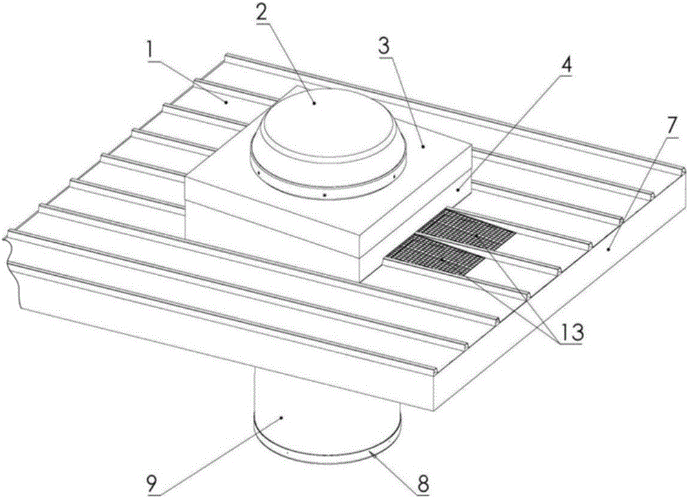
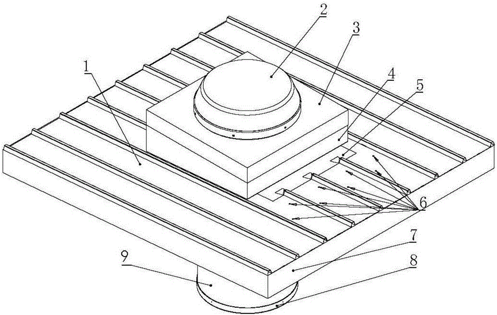
[0024] to combine figure 2 , the light steel roof construction of this embodiment installs the roof water-proof structure of the light pipe, which is installed on the light steel roof 1, and the light steel roof 1 is provided with reinforcing ribs in parallel and evenly distributed, and the light steel roof 1 is arranged along the reinforcing ribs. The direction of extension is inclined downwards.

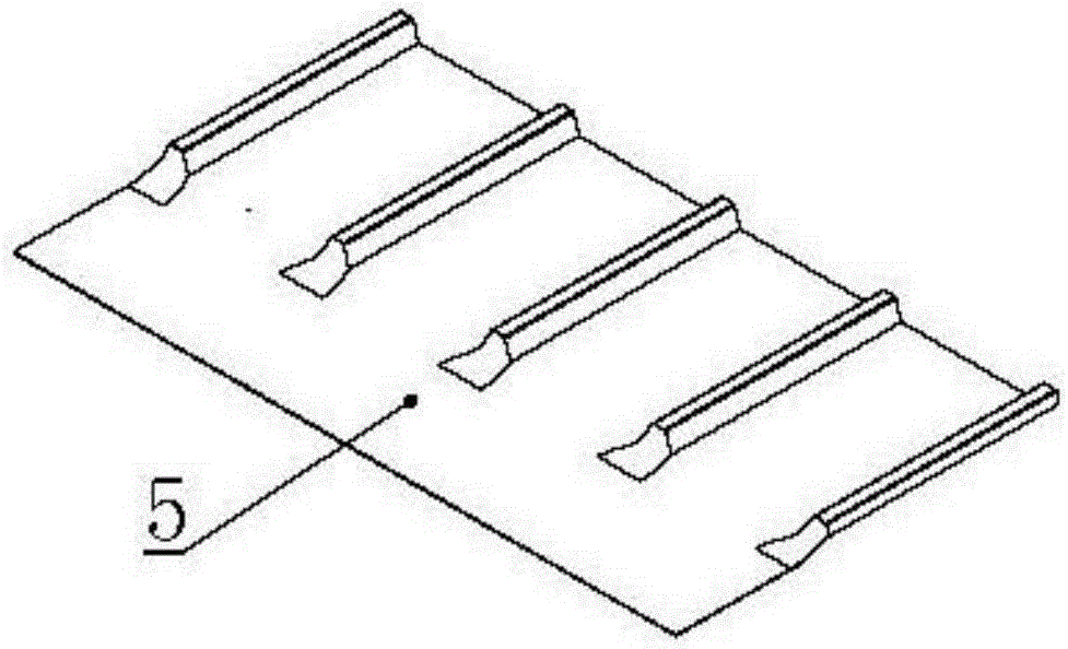
[0025] to combine Figure 2 to Figure 4 , the roof anti-water structure mainly includes a daylighting cover 2, a rain cap 3, a light guide 9, a diffuser 8, a podium 4 and a drainage sheet 5. The first end of the drainage sheet 5 is formed with accommodating grooves that match the reinforcing ribs of the light steel roof 1 to fit and fix the light steel roof 1, and the second end has a planar structure, and the light steel roof 1 corresponds to the drainage The position of the second end of the sheet is also a planar structure; the pier 4 is installed on the top outside of the li...

Embodiment 2

[0031] to combine Figure 6 The roof water-proof structure of the light steel roof building installation light guide of this embodiment is basically the same as that of the first embodiment, including a lighting cover 2, a rainproof cap 3, a light guide 9, a diffuser 8, a podium 4 and a drainage sheet 5. The plinth 4 is installed on the top outside of the light steel roof 1 , and the pier 4 and the light steel roof 1 are provided with through holes, and then the light guide 9 is installed through the light steel roof 1 .

[0032] The main difference is that the first end of the drainage sheet 5 is covered and installed on the upper side of the outer end of the light steel roof 1, and the connection between the drainage sheet 5 and the light steel roof 1 is also sealed, which can also achieve the technical effect of drainage.

[0033] to combine Figure 7, a drainage groove is formed between two adjacent reinforcing ribs on the light steel roof 1, and the rainwater flows alon...


PUM


Abstract

The invention relates to a roof water accumulation preventing structure with a tubular daylighting system of a lightweight steel roof building. The roof water accumulation preventing structure is mounted on a lightweight steel roof with reinforcing ribs, comprises a lighting cover, a rain shield, the tubular daylighting system, a diffuser and a pier base, and is also provided with a drainage sheet. The drainage sheet is arranged in front of the pier base along a high-to-low extension direction of the reinforcing ribs of the lightweight steel roof. A first end of the drainage sheet is in tight fitting with the lightweight steel roof, a second end thereof is of a planar structure to avoid water accumulation between every two adjacent reinforcing ribs and is hermetically connected to the pier base and the lightweight steel roof to enable the lightweight steel roof to be connected to the pier base through the drainage sheet, and water flow on the lightweight steel roof flows to the side face of the pier base through guiding of the planer structure, so that the problems of proneness to water accumulation, leakage and smudging of a tubular daylighting system structure are solved.

Description

technical field [0001] The invention belongs to the technical field of energy-saving lighting equipment, and in particular relates to a roof water-proof structure for installing a light pipe on a light steel roof building. Background technique [0002] In recent years, due to energy shortages, how to save energy and reduce carbon emissions has become a widely discussed topic. Most of the lighting in industrial plants uses high-wattage lighting as the main lighting, and then uses auxiliary light sources in details. This lighting method has low energy consumption and lighting The cost of expenditure is considerable. Therefore, a light guide lighting equipment has appeared on the market. Using this equipment, the natural light source during the day can be introduced into the factory building as the main lighting source, so as to achieve the purpose of energy saving and carbon reduction. [0003] The utility model patent of authorized notification number CN 203893063 U discloses...

Claims


Application Information

Patent Timeline
Patent Type & Authority Applications(China)
IPC IPC(8): E04D13/04E04D13/00E04D13/16F21S11/00
CPCE04D13/0481E04D13/00E04D13/16F21S11/007
Inventor 刘敬伟王庆江邱爵廖宋凌辉
Owner XIAMEN CITY YAPHA OPTOELECTRONICS TECH
Why Eureka
Try Eureka