Ground tile laying robot

A technology of robots and ceramic tiles, which is applied in the direction of architecture and building construction, can solve the problems of reduced work quality, structure without ceramic tiles, low work efficiency, etc., and achieve the effect of improving work efficiency and simple and efficient working methods

Inactive Publication Date: 2017-05-31
台州大顺建设有限公司 +1
View PDF6 Cites 13 Cited by
  • Summary
  • Abstract
  • Description
  • Claims
  • Application Information

AI Technical Summary

Problems solved by technology

[0002] Nowadays, more and more occasions need to lay floor tiles. At present, floor tiles in many building constructions are laid by hand, which requires certain skills of workers. Unskilled workers may cause gaps between floor tiles. The gaps are uneven and uneven, and the work efficiency is relatively low and the progress is slow. Therefore, a machine that replaces manual work is needed to complete the brick laying work.
For example, the invention patent of patent application number 201610769794.7 "a horizontal floor tile laying device for house construction" includes: mobile car body, adjusting frame, electronic level controller, mounting plate, beam, downward pressure cylinder, suction plate, Suction cups, etc., in the laying process, because they cannot be installed and cannot place tiles, the work efficiency is low, and they do not have the structure to tamp the tiles after laying, resulting in a decline in work quality. Therefore, a work efficiency is required. taller machine

Method used


Image

  • Ground tile laying robot
  • Ground tile laying robot
  • Ground tile laying robot

Examples


Embodiment

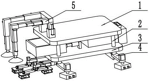
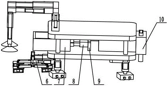
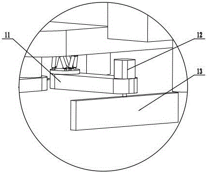
[0019] Such as figure 1 , figure 2 , image 3 , Figure 4 , Figure 5 , Image 6 , Figure 7 , Figure 8 As shown, a floor tile laying robot includes an upper plate 1, a pillar 2, a lower plate 3, four walking mechanisms 4, a laying mechanism 5, a compaction mechanism 6, a tile frame 7, two first electric cylinders 8, two The electric cylinder base 9, the cement tank 10, the rear rod 11, the first servo motor 12, the scraper 13, the upper end plate 14, the second electric cylinder 15, the lower end plate 16, are characterized in that: the upper plate 1 and the lower plate There are four pillars 2 between 3, which are located at the four corners; the cement box 10 is installed at the front end of the lower board 3, and the outlet position is set at the front end of the lower board 3, at the position below the cement box 10, namely An upper end plate 14 is installed on the lower surface of the lower plate 3, a lower end plate 16 is arranged under the upper end plate 14, and six ...


PUM


Abstract

A ground tile laying robot comprises an upper plate, columns, a lower plate, four walking mechanisms, a laying mechanism, a compaction mechanism, ceramic tile frames, two first electrical cylinders, two electrical cylinder bases, a cement box, a rear rod, a first servo motor, a scraping plate, an upper end plate, second electrical cylinders and a lower end plate and is characterized in that four columns are arranged between the upper plate and the lower plate and are located at the positions of four corners respectively, the four walking mechanisms are installed at the positions of four corners of the lower surface of the lower plate, the two electrical cylinder bases are arranged at the position, close the back, of the cement box on the lower plate, the rear-end portions of the two first electrical cylinders are installed on the electrical cylinder bases respectively, and the front-end portions of the two first electrical cylinders are installed on connecting parts of the ceramic tile frames. The ground tile laying robot is provided with the ceramic tile frames, the working efficiency of the robot can be improved by pre-placing ceramic tiles, the ceramic tiles in the ceramic tile frames are automatically laid on the ground through united work of the laying mechanism and the compaction mechanism, and a working mode is simple and efficient.

Description

Technical field [0001] The invention relates to the field of building decoration machinery, in particular to a floor tile laying robot. Background technique [0002] Nowadays, more and more occasions need to lay floor tiles. At present, many floor tiles in construction are laid by hand. This requires the skills of workers. Unskilled workers may cause gaps between floor tiles. Due to the uneven gaps and uneven heights, the work efficiency is relatively low, and the progress is slow, so a machine instead of manual is needed to complete the tile work. For example, the invention patent "A horizontal floor tile laying device for house construction" with the patent application number 201610769794. 7 includes: a mobile car body, an adjusting frame, an electronic level controller, a mounting plate, a beam, a downward pressure cylinder, a suction plate, Suction cups, etc., during the laying process, because the device itself cannot be placed, the work efficiency is low, and there is no s...

Claims


Application Information

Patent Timeline
Patent Type & Authority Applications(China)
IPC IPC(8): E04F21/22
CPCE04F21/22
Inventor 不公告发明人
Owner 台州大顺建设有限公司
Why Eureka
Try Eureka