
A kind of construction site construction concrete steel structure and construction pouring method

A construction site and concrete technology, applied in building construction, construction, building material processing and other directions, can solve the problems of heavy components, many hidden safety hazards, and many cross-operations, etc., and achieve strong compressive and tensile strength, easy to use The effect of fixed connection and simple connection structure

Active Publication Date: 2018-12-21
龙元明筑科技有限责任公司
View PDF4 Cites 0 Cited by
  • Summary
  • Abstract
  • Description
  • Claims
  • Application Information

AI Technical Summary

Problems solved by technology

Its characteristic is that there is a concrete shell outside the steel structure. Because the steel concrete structure has good mechanical properties, it is especially suitable for earthquake areas. Although the steel concrete structure has many advantages compared with the traditional structure, there are still the following points Disadvantages: The traditional reinforced structure node reinforcement structure is more complicated, and the engineering construction is difficult. The connection structure has always been the most difficult problem to solve in the composite structure, and further research is needed; there are steel plate structures and steel bars in the column-beam-wall. How to deal with the intersecting process between the steel plate and the steel bar is another construction problem. How to ensure the construction quality of the steel plate and the steel bar; The screening and experimentation required a large amount of engineering; in addition, the components were heavy, there were many cross-operations, and there were many safety hazards in the construction, so targeted safety measures were needed to ensure safe construction; finally, the steel bars were dense, and there were many penetrating structures, which gave The pouring of concrete poses great difficulties

Method used


Image

  • A kind of construction site construction concrete steel structure and construction pouring method
  • A kind of construction site construction concrete steel structure and construction pouring method
  • A kind of construction site construction concrete steel structure and construction pouring method

Examples


Embodiment 1

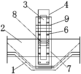
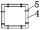
[0024] Embodiment 1: A construction site construction concrete steel structure, including a foundation raft 1, the cross-sectional shape of the foundation raft 1 is U-shaped, and gradually opens from the bottom upward to the outside, and the top of the foundation raft 1 A reinforced concrete base beam 2 is also installed, and a column-shaped steel 3 is installed at the center of the foundation raft 1, and the outside of the column-shaped steel 3 is provided with a steel bar layer 4, and the steel bar layer 4 is fixed and hinged together by tie wires 5, And the hinge specification of the steel bar layer 4 is 1000 mesh, and the column outer stirrup 6 is also arranged between the column shaped steel 3 and the steel bar layer 4, and the column outer stirrup 6 is orthogonal to the steel bar layer 4 and the column shaped steel 3 And they are connected together by welding, and the connection between the reinforced concrete base beam 2 and the column steel 3 is connected through the th...

Embodiment 2

[0031] Embodiment 2: The difference from Embodiment 1 is: a construction site construction concrete steel structure, the distance between the column steel and the reinforcement layer is 1500mm, and the distance between the T-shaped steel and the reinforced concrete base beam is 800mm.

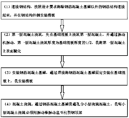
[0032] A concrete pouring method for construction site construction, in the step (1), the distance between the formwork and the outer steel structure is 7.5cm; in the steps (2) and (4), the vibration machine The vibration time is 25 seconds, and the construction time between step (2) and step (4) is 2h.

Embodiment 3

[0033] Embodiment 3: The difference from Embodiment 1 is: a construction site construction concrete steel structure, the distance between the column steel and the reinforcement layer is 1600mm, and the distance between the T-shaped steel and the reinforced concrete base beam is 850mm.

[0034] A concrete pouring method for construction site construction, in the step (1), the distance between the formwork and the outer steel structure is 10cm; in the steps (2) and (4), the vibrating machine vibrates The time is 30 seconds, and the construction time between step (2) and step (4) is 3h.

[0035] It should be noted that the steel structure of the present invention is multi-layer superimposed, that is, all the steel structures are not assembled at the beginning, but during the concrete pouring process, the steel bars are bundled while pouring the concrete. The first feature is mainly manifested on the concrete foundation beam, which is mainly because the concrete foundation beam is...


PUM


Abstract

The invention discloses a concrete-steel structure and pouring method for construction on a construction site. The concrete-steel structure comprises a foundation raft, and the section of the foundation raft is in a U shape and is splayed outwards gradually from bottom to top. A reinforced concrete base beam is further mounted at the top of the foundation raft. Columnar steel is mounted at the center of the foundation raft. A steel wire layer is arranged outside the columnar steel and is formed by fixedly hinging binding wires together. Extra-column stirrups are further arranged between the columnar steel and the steel wire layer. The reinforced concrete base beam and the columnar steel are connected through a through hole which is formed in the reinforced concrete base beam, and an anchor bolt is mounted in the through hole. A three-dimensional orthogonal structure is adopted, concrete is poured layer by layer during pouring, steel bar structures are connected in an overlap welding mode in the pouring process, and thus the probability that the interiors of the steel bar structures are hindered by concrete latex is further lowered; and all the components supplement one another, the crush resistance and the tension resistance of the whole structure are higher, and a good mechanical property is achieved.

Description

technical field [0001] The invention relates to the technical field of concrete pouring technology, in particular to a construction site construction concrete steel structure and a construction pouring method. Background technique [0002] The structure in which steel bars are arranged in concrete is called concrete steel bar composite structure, which is the most widely used high-rise building concrete structure at present. Its characteristic is that there is a concrete shell outside the steel structure. Because the steel concrete structure has good mechanical properties, it is especially suitable for earthquake areas. Although the steel concrete structure has many advantages compared with the traditional structure, there are still the following points Disadvantages: The traditional reinforced structure node reinforcement structure is more complicated, and the engineering construction is difficult. The connection structure has always been the most difficult problem to solve...

Claims


Application Information

Patent Timeline
Patent Type & Authority Patents(China)
IPC IPC(8): E04G21/00E04B1/30
CPCE04B1/30E04G21/00
Inventor 汤沛林鑫焱
Owner 龙元明筑科技有限责任公司
Learn More