Push plate clamping rod mechanism for garage carrier

A carrier and clamping rod technology, which is applied in the field of garage carriers, can solve the problems of high processing and maintenance costs and complex structures, and achieve the effects of easy processing and maintenance, simple structure, and reduced production and maintenance costs

Inactive Publication Date: 2017-05-31
HUNAN DISHENG IND EQUIP
View PDF4 Cites 1 Cited by
  • Summary
  • Abstract
  • Description
  • Claims
  • Application Information

AI Technical Summary

Problems solved by technology

The push plate clamping rod mechanism in the existing tire-holding type carrier has the disadvantages of complex structure, high processing and maintenance costs, etc.

Method used


Image

  • Push plate clamping rod mechanism for garage carrier
  • Push plate clamping rod mechanism for garage carrier
  • Push plate clamping rod mechanism for garage carrier

Examples


Embodiment Construction

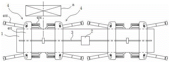
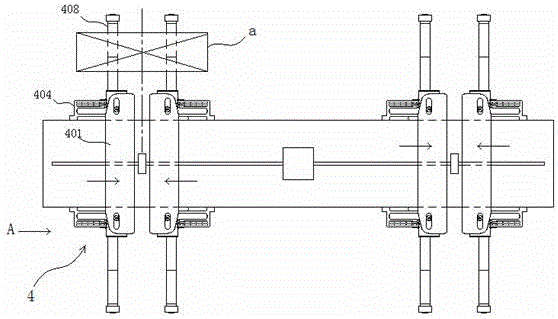
[0017] Holding a tire type carrier such as figure 1 Shown, comprise car body 1, be located at the front and rear two groups of push pedal clamping rod mechanisms on the car body 1 and the screw power mechanism that is made up of screw mandrel 3 and motor 2, every group of push pedal clamping rod mechanisms includes two relative The moving push plate clamp mechanism 4 is composed of each push plate clamp mechanism 4 including a thrust plate 401, a track seat 404 positioned at both sides of the car body 1, two upper and lower parts driven by the thrust plate 401 and matched with the track seat 404. A clamping rod 408, wherein the thrust plate 401 is connected with the screw mandrel 3, and two push pedal clamping rod mechanisms 4 that do relative motion in the two groups of push pedal clamping rod mechanisms are driven by the screw rod power mechanism.

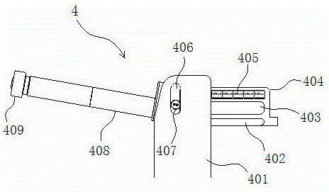
[0018] Push plate clamp mechanism 4 such as Figure 3 to Figure 5 As shown, it includes a thrust plate 401, a clamping rod 408...


PUM


Abstract

The invention discloses a push plate clamping rod mechanism for a garage carrier. The mechanism comprises a toggle plate, a clamping rod and a rail base. Linear rails are arranged on the rail base. Limit steps which are shorter than the linear rail are arranged at the side along the linear rail, of the rail base. A slide column which coordinates with the linear rail on the rail base and a stress column which coordinates with the toggle plate are separately arranged at the bottom and upper portion of the clamping rod. A linear edge which coordinates with the limit steps is arranged at the end portion. According to the push plate clamping rod mechanism for the garage carrier, the clamping rod is driven to coordinate with the linear rails and the limit steps on the rail base through the motion of the toggle plate, and the tire clamping function is achieved through the rotating opening and linear motion of the clamping rod. The mechanism is simple in structure, easy to process and maintain, and capable of reducing production and maintenance cost.

Description

technical field [0001] The invention belongs to a garage transporter, in particular to a push plate clamping rod mechanism of a garage transporter. Background technique [0002] The garage mover is a special equipment for moving cars in the three-dimensional garage. The tire-holding carrier is a kind of garage carrier. Its working principle is to use the screw power device to drive the thrust plate in relative motion, and drive the two clamping rods to rotate and open along the arc track and straight track, and then go straight. Lift the vehicle by holding the tires, then move the vehicle by itself. The push plate clamping rod mechanism in the existing tire-holding type carrier has the disadvantages of complex structure, high processing and maintenance cost, and the like. Contents of the invention [0003] The purpose of the present invention is to provide a simple structure, easy to process the push plate clamping rod mechanism of the garage carrier. [0004] The push ...

Claims


Application Information

Patent Timeline
Patent Type & Authority Applications(China)
IPC IPC(8): E04H6/18E04H6/30
CPCE04H6/182E04H6/305
Inventor 唐振宇
Owner HUNAN DISHENG IND EQUIP
Why Eureka
Try Eureka