Quakeproof platform for tower

A technology for platforms and towers, which is applied in the field of anti-vibration platforms for poles and towers. It can solve the problems of uneven settlement, time-consuming and labor-intensive installation process, and easy settlement of the base, so as to improve structural stability and reliability, prevent breakage or dumping, and reduce oxidation. or the effect of corrosion

Inactive Publication Date: 2017-05-31
STATE GRID HENAN ELECTRIC ZHOUKOU POWER SUPPLY
View PDF14 Cites 6 Cited by
  • Summary
  • Abstract
  • Description
  • Claims
  • Application Information

AI Technical Summary

Problems solved by technology

[0002] At present, the tower design and structural safety and stability construction of 35KV and below power transmission and distribution lines in the power grid are relatively weak. The towers for power transmission and wiring are all equipped with thick cylinders at the bottom, with brackets at the top, and tree-like shapes at high altitude. It is suitable for erecting wires and cables, the bottom of which is connected by bolts to the foundation that is simply laid underground. However, this traditional rigid fixing method between the tower and the ground is difficult to resist the vibration of the foundation or the occurrence of earthquake disasters. When an earthquake occurs, the foundation is often cracked and damaged. Uneven settlement, etc.; when natural disasters such as strong winds, heavy snow, heavy rain, and ice cover occur, the tower will be tilted and overturned like a "domino" effect. Power outages seriously endanger the safety of electricity and the electricity consumption of residents in production and life, and bring immeasurable losses to the national economy.
On August 14, 2013, a tornado hit Pushi Town, Luxi County, Xiangxi Autonomous Prefecture. After the tornado, the roofs of Neiwa houses in the town were overturned, and the utility poles collapsed in rows and fell on the roofs of residents or trees. More than 5 The 10 kV line was affected by the disaster, affecting nearly 100,000 residents in four villages and towns for production and living electricity. However, the current common method is to prefabricate concrete at the base, and then connect the bottom of the pole through the flange. If the concrete base is small It is easy to settle, and if it is very large, it will waste a lot of resources, and the flange connection method is easy to break under conditions such as strong winds and vibrations, and there are still major safety hazards. Therefore, how to design a new type of tower structure to make the disaster-resistant ability greatly improved
The disadvantage of this structure is that the connection between the pole and the base is still rigid, and the earthquake resistance is not strong in the face of the shear wave and longitudinal wave of the earthquake
The disadvantage of this structure is: the structure is complicated, and the installation process is time-consuming and laborious

Method used


Image

  • Quakeproof platform for tower
  • Quakeproof platform for tower
  • Quakeproof platform for tower

Examples


Embodiment 1

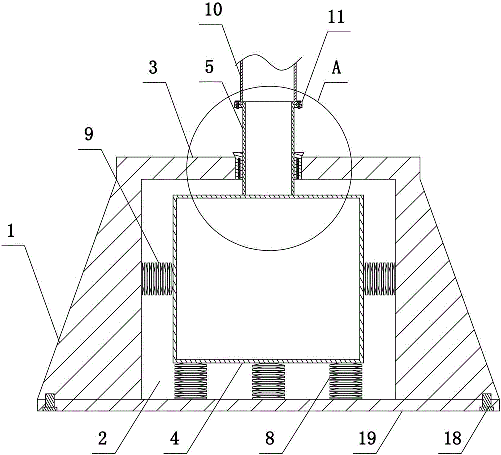
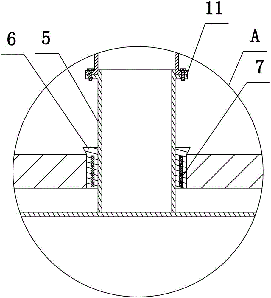
[0026] Such as figure 1 and figure 2 As shown, the present invention includes a support base 1, a shock absorbing structure and an adapter structure 10. The adapter structure 10 can use a columnar hollow steel pipe. Cuboid columnar structure, the upper end surface of the support base 1 is integrally formed with a cover plate 3, a through hole is set in the center of the cover plate 3, the through hole is a circular structure, the width of the accommodation cavity 2 is greater than the diameter of the through hole; the shock absorbing structure includes setting a shock absorbing seat 4 and the connecting rod 5, the shock-absorbing seat 4 is a rectangular columnar structure, the connecting rod 5 is a circular structure, the shock-absorbing seat 4 is installed in the accommodation chamber 2, and the lower end of the connecting rod 5 extends into the accommodation chamber 2 and is fixed with the shock-absorbing seat 4 connection, the upper end of the connecting rod 5 extends out...

Embodiment 2

[0029]The present invention includes a support base 1, a shock absorbing structure and a transfer structure 10. The support base 1 is a circular truncated structure, and the center of the support base 1 is provided with an accommodation cavity 2, which is a rectangular columnar structure, and the upper end surface of the support base 1 is integrally formed with a cover plate. 3. A through hole is set in the center of the cover plate 3, the through hole is a circular structure, and the width of the accommodating cavity 2 is larger than the diameter of the through hole; the shock absorbing structure includes a shock absorbing seat 4 and a connecting rod 5, and the shock absorbing seat 4 is a rectangular parallelepiped column structure, the connecting rod 5 is a circular structure, the shock-absorbing seat 4 is installed in the accommodation chamber 2, the lower end of the connecting rod 5 extends into the accommodation chamber 2 and is fixedly connected with the shock-absorbing se...

Embodiment 3

[0032] The structure of this embodiment is basically the same as that of Embodiment 1, the difference is: as Figure 4 As shown, four first protrusions 12 (two are shown in the figure) are arranged on the outer wall of the shock absorber 4, four second protrusions 13 are arranged on the inner wall of the accommodation cavity 2, and the second disc spring group 9 is four and its two ends are respectively socketed with the first protrusion 12 and the second protrusion 13. During installation, the second disc spring group 9 is retracted by the hydraulic or pneumatic clamping device in the prior art, and it is sleeved on the first protrusion 12 and the second protrusion 13. When an earthquake occurs, this structural design is beneficial Improve the stability of the second disc spring group 9.


PUM


Abstract

The invention discloses a quakeproof platform for a tower. The quakeproof platform for the tower comprises a support base (1), a damping structure and a connecting structure (10). An accommodation cavity (2) is formed in the center of the support base (1), a cover plate (3) is installed on the upper end face of the support base (1), and a through hole is formed in the center of the cover plate (3). The damping structure comprises a damping seat (4) and a connection rod (5), the damping seat (4) is installed in the accommodation cavity (2), the upper end of the connection rod (5) stretches out of the through hole, a sealing ring (6) is installed between the connection rod (5) and the cover plate (3), a reinforcing layer (7) which is interwoven transversely and longitudinally is installed in the sealing ring (6), and a plurality of disc spring buffering pieces are installed between the damping seat (4) and the accommodation cavity (2). According to the quakeproof platform for the tower, by installing disc spring buffering pieces between the support base and the damping seat and installing the sealing ring between the connection rod and the cover plate, rigid damage of transverse waves and longitudinal waves of earthquakes to electric poles is effectively prevented, and meanwhile, quakeproof platform for the tower has the advantages that manufacturing is easy, and installing is convenient.

Description

technical field [0001] The invention belongs to the technical field of power transmission lines, and in particular relates to a tower anti-vibration platform. Background technique [0002] At present, the tower design and structural safety and stability construction of 35KV and below power transmission and distribution lines in the power grid are relatively weak. The towers for power transmission and wiring are all equipped with thick cylinders at the bottom, with brackets at the top, and tree-like shapes at high altitude. It is suitable for erecting wires and cables, the bottom of which is connected by bolts to the foundation that is simply laid underground. However, this traditional rigid fixing method between the tower and the ground is difficult to resist the vibration of the foundation or the occurrence of earthquake disasters. When an earthquake occurs, the foundation is often cracked and damaged. Uneven settlement, etc.; when natural disasters such as strong winds, he...

Claims


Application Information

Patent Timeline
Patent Type & Authority Applications(China)
IPC IPC(8): E04H12/22E04H9/02E04B1/98
CPCE04H12/2276E04H9/021
Inventor 施学召赵志健李峰
Owner STATE GRID HENAN ELECTRIC ZHOUKOU POWER SUPPLY
Why Eureka
Try Eureka