Power tong combined slips

A technology of combining clamps and power tongs, applied in drill pipe, casing, drill pipe, etc., can solve the problems of inability to ensure reliable and effective clamping of drill pipe, inability to achieve rapid on-site replacement, easy to wear and need to be replaced frequently, etc. The structure is stable and reliable, the effective contact area is increased, and the clamping is uniform and reliable.

Active Publication Date: 2018-10-16
BC P INC CHINA NAT PETROLEUM CORP +1
View PDF5 Cites 0 Cited by
  • Summary
  • Abstract
  • Description
  • Claims
  • Application Information

AI Technical Summary

Problems solved by technology

[0004] The power tongs for continuous circulation drilling are different from those for conventional drilling. The power tongs for continuous circulation drilling can only clamp the drill pipe body, and the clamping force must be strictly controlled when the power tongs clamp the drill pipe to ensure that the slips of the power tongs After tightening the drill pipe, it can neither slip nor squeeze the drill pipe. It is also required that the indentation of the slips on the drill pipe should be as small as possible, and the drill pipe should not be bitten. It may be large, and the clamping should be more uniform and reliable; at the same time, during the continuous cycle drilling process, the power tongs make up and break out frequently, and the slips are easy to wear and need to be replaced frequently. Quick replacement on site, so as not to affect the construction efficiency, that is, the slips need to be disassembled and installed easily; it can be seen that the slips of the power tongs for continuous circulation drilling have higher requirements than those of conventional drilling power tongs. However, the slips in the prior art When the power tong slips are used for continuous circulation drilling, they can only disassemble the tooth plate or disassemble the slips as a whole, which cannot realize quick replacement on site, and cannot guarantee reliable and effective clamping of the drill pipe

Method used


Image

  • Power tong combined slips
  • Power tong combined slips
  • Power tong combined slips

Examples


Embodiment Construction

[0029] The following will clearly and completely describe the technical solutions in the embodiments of the present invention with reference to the accompanying drawings in the embodiments of the present invention. Obviously, the described embodiments are only some, not all, embodiments of the present invention. Based on the embodiments of the present invention, all other embodiments obtained by persons of ordinary skill in the art without making creative efforts belong to the protection scope of the present invention.

[0030] Unless otherwise defined separately, directions such as up, down, front, back, left, and right mentioned herein are all in accordance with the present invention. figure 2 The directions of up, down, front, back, left, and right in the text shall prevail, and shall be explained together here.

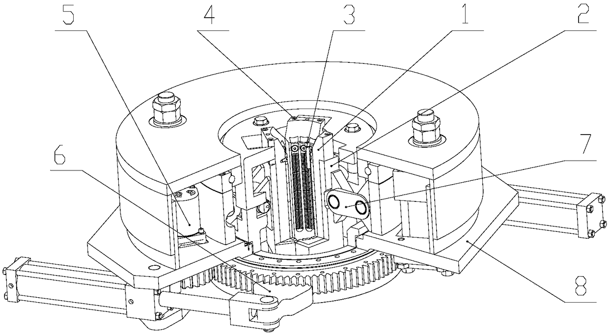
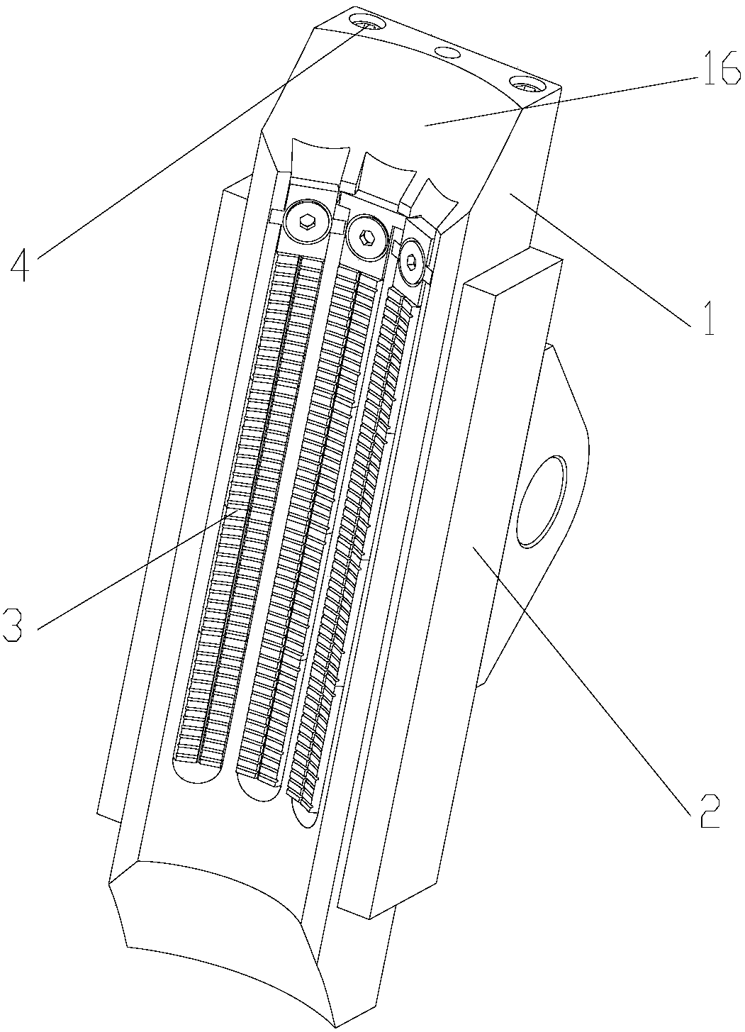
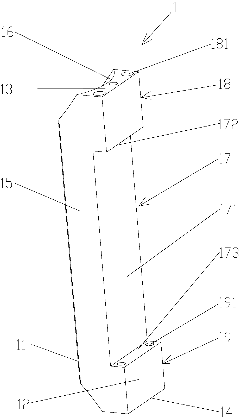
[0031] Such as Figure 1 to Figure 4 As shown, the present invention provides a combination slip of a power tong, which includes: a rear slip body 2, which is h...


PUM


Abstract

The invention provides a combined clamping tile for power tongs. The combined clamping tile comprises a rear clamping tile body and a front clamping tile body, wherein the rear clamping tile body is hinged with the power tongs; a second groove is concaved in a front wall of the rear clamping tile body; the front clamping tile body is located on the front side of the rear clamping tile body; a plurality of clamping tile toothed plates for clamping a drill rod are arranged on the front wall of the front clamping tile body; a first groove is concaved in a rear wall of the front clamping tile body; the first groove of the front clamping tile body is blocked with the second groove of the rear clamping tile body; and the front clamping tile body is detachably connected with the rear clamping tile body. The combined clamping tile for power tongs can be used for reliably and effectively clamping the drill rod; the clamping tile can be quickly replaced; the structure is simple; the operation is convenient; and the construction efficiency is high.

Description

technical field [0001] The invention relates to the field of drilling equipment in the petroleum industry, in particular to a combined slip of a power tong for continuous circulation drilling. Background technique [0002] Continuous circulation drilling achieves stable equivalent circulation density and uninterrupted cuttings discharge during the entire drilling period, which improves wellbore conditions and drilling safety in an all-round way. This technology is especially suitable for safe drilling under the condition of narrow drilling fluid density window. In addition, in extended-reach wells, horizontal wells, high-pressure and high-temperature wells, and underbalanced wells, this technology can ensure that the well wall does not collapse to the greatest extent, avoid stuck pipe, reduce drilling accidents, and increase the ROP. [0003] The power tong is the key part of the main engine of the continuous circulation drilling device. It is mainly composed of four parts:...

Claims


Application Information

Patent Timeline
Patent Type & Authority Patents(China)
IPC IPC(8): E21B19/10
CPCE21B19/10
Inventor 肖建秋任荣权马金山胡志坚齐金涛郗凤亮梁国红徐朝阳张晔邵强王爱国刘继亮
Owner BC P INC CHINA NAT PETROLEUM CORP
Why Eureka
Try Eureka