Engine structure for vehicle

A technology for engines and vehicles, which is applied in the direction of engine components, combustion engines, machines/engines, etc., and can solve problems such as adverse effects of engine fuel efficiency

Active Publication Date: 2017-05-31
HYUNDAI MOTOR CO LTD +1
View PDF10 Cites 0 Cited by
  • Summary
  • Abstract
  • Description
  • Claims
  • Application Information

AI Technical Summary

Problems solved by technology

[0007] It has been found that, in a method of injecting fuel from a nozzle hole of an injector provided in an intake port, when the fuel injected from the injector adheres to the flow path of the intake port, there is an adverse effect on the fuel efficiency of the engine. influences

Method used


Image

  • Engine structure for vehicle
  • Engine structure for vehicle

Examples


Embodiment Construction

[0021] The following description is merely exemplary in nature, and is not intended to limit the disclosure, application, or uses. It should be understood that throughout the drawings, corresponding reference numerals indicate like or corresponding parts and features.

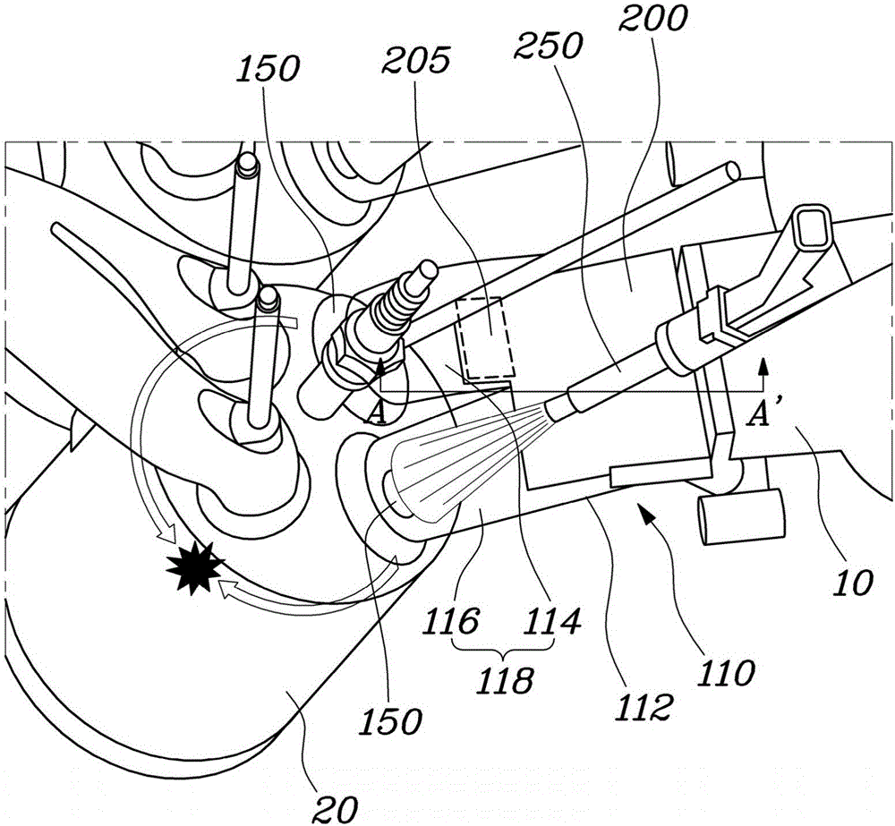
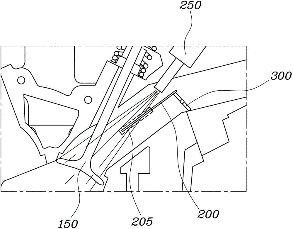
[0022] Figure 1 to Figure 2 An engine structure for a vehicle according to the present disclosure is shown. The engine structure includes: intake port 110 , port plate 200 , and injector 250 . The intake port 110 is configured such that a single flow path 112 in an upstream portion of the intake port branches into a pair of branched flow passages 118 (ie, a pair of branched ports) in a downstream portion of the intake port, and the port plate 200 forms is plate-shaped and disposed in the single flow path 112 of the intake port 110 . Specifically, the port plate 200 is arranged longitudinally parallel to the flow path of the intake port 110 so that the flow path of the intake port 110 is divided into an uppe...


PUM


Abstract

The present disclosure provides an engine structure for a vehicle. The engine structure includes: an intake port, a port plate provided in the single flow path of the intake port, and an injector. The port plate is longitudinally parallel to the flow path of the intake port so as to divide the flow path of the intake port into upper and lower flow paths, and the port plate includes an extension portion formed on part of a downstream end of the port plate such that the extension portion of the downstream end of the port plate extends longer than other portion of the downstream end of the port plate. In particular, the injector is provided in the intake port, and sprays fuel beyond the extension portion so as to inhibit the fuel from adhering to the port plate.

Description

technical field [0001] The present disclosure generally relates to an engine structure for a vehicle. More particularly, the present disclosure relates to an engine structure for a vehicle configured to inhibit or prevent fuel from adhering to a port. Background technique [0002] The statements in this section merely provide background information related to the present disclosure and may not constitute prior art. [0003] In general, these technologies using various methods of injecting fuel, methods of controlling intake air, and structures of intake ports have been developed and applied to improve engine efficiency in vehicles, such as fuel efficiency, particularly, engines of vehicles fuel efficiency in . [0004] As a technique for improving the engine efficiency of a vehicle, a method of mixing fuel introduced into a combustion chamber and intake air has been developed, and a method of uniformly dispersing fuel of the air-fuel mixture has been developed, thereby imp...

Claims


Application Information

Patent Timeline
Patent Type & Authority Applications(China)
IPC IPC(8): F02B31/04F02B31/06F02M61/14
CPCF02B31/04F02B31/06F02M61/145F02B31/085F02F1/4242F02F1/425Y02T10/12
Inventor 秋东昊朱南鲁李亮杰朴钟一金容焄河明九韩东熙
Owner HYUNDAI MOTOR CO LTD
Why Eureka
Try Eureka