Noise reduction device for industrial fan

A fan and noise reduction technology, which is applied to parts of pumping devices for elastic fluids, pump devices, mechanical equipment, etc., can solve problems such as motor failure, obvious, burnt, etc., reduce manufacturing costs, ensure working environment, The effect of simple structural design

Inactive Publication Date: 2017-05-31
吴光明
View PDF5 Cites 5 Cited by
  • Summary
  • Abstract
  • Description
  • Claims
  • Application Information

AI Technical Summary

Problems solved by technology

[0002] Noise control is necessary for existing industrial environmental protection. The noise of industrial fans is particularly obvious, and the main sources of noise are: air inlet, fan body, motor and air outlet; the existing treatment method is to use the fan and motor as a suction partition Acoustic cover, ventilation mufflers are arranged at the air inlet and outlet, but this method has brought another negative effect, resulting in poor heat dissipation of the motor, causing motor failure or even burning. In order to solve this problem, the existing technology is A forced ventilation muffler is added to the sound insulation room of the fan and motor for heat dissipation (such as figure 1 shown)
With such a set of equipment, the cost of noise control has increased a lot, and when the maintenance personnel enter the soundproof room for maintenance in summer, the indoor temperature is as high as 60 degrees, which makes the maintenance personnel unable to stay inside for a long time, and the high temperature also affects the service life of the equipment. , in view of the above-mentioned shortcomings existing in the prior art, there is a need for a noise reduction device that can reduce the cost of environmental protection treatment, effectively reduce noise, ensure the temperature of the soundproof room, and ensure the life of the equipment

Method used


Image

  • Noise reduction device for industrial fan
  • Noise reduction device for industrial fan

Examples


Embodiment 1

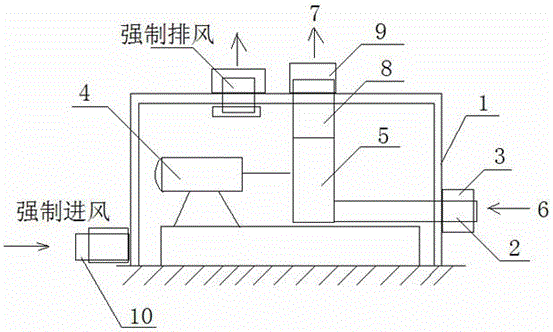
[0014] Such as figure 1 As shown, in the structure adopted in the prior art, the sound-absorbing and insulating room 1 is provided with an air inlet pipe 2 near the side of the fan 5, and the air inlet pipe 2 is connected to the air inlet 6 of the fan, and the air inlet muffler 3 is installed on the air inlet pipe 2. The air outlet muffler 9 is installed on the air outlet pipe 8, the heat dissipation air inlet pipe 10 is installed on the motor side, the air inlet muffler is installed on the heat dissipation air inlet pipe 10, the forced air exhaust pipe is installed on the top of the sound insulation room 1, and the heat dissipation is installed. The fan performs forced exhaust, and a muffler is installed on the forced exhaust pipe. It can be seen that in the existing technology, the structure is assisted, the equipment investment is large, and the forced fan is required, which consumes a lot of energy. Moreover, the temperature in the sound absorption and insulation room is k...

Embodiment 2

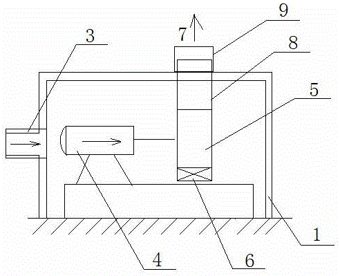
[0021] For some extreme cases, such as when circulating air is used, such as figure 1 The air inlet pipe of figure 2 The air inlet of the fan, when the fan is working, it will enter the air from the air inlet of the fan and the air inlet pipe. figure 2 The set air inlet and air inlet muffler structure will still generate negative pressure through the suction of the fan air inlet to take away the heat of the motor.


PUM


Abstract

The invention discloses a noise reduction device for an industrial fan. A sound absorption and insulation chamber is arranged outside the fan and a motor; an air inlet is formed in a position facing the non-output end of the motor, in the sound absorption and insulation chamber; an air inlet silencer is arranged on the air inlet; the output end of the motor is connected with the fan; the air inlet of the fan is formed in the sound absorption and insulation chamber; an air outlet is connected to the outside of the sound absorption and insulation chamber through an air outlet pipe; and an air outlet silencer is arranged on the air outlet pipe. The noise reduction device disclosed by the invention has the advantages that the structural design is simple; the whole device is not provided with a forced air inlet heat dissipation motor in the prior art, and a plurality of air inlet pipes, air outlet pipes and silencers arranged on the air inlet pipes and the air outlet pipes are reduced, so that the manufacturing cost is reduced, and the absorption and the insulation of the noise of the motor and the fan are effectively guaranteed; indoor temperature can be kept within 30 DEG C in summer, so that the temperature in the sound absorption and insulation chamber is greatly lowered, and the service life of equipment and the working environment for maintenance staff are guaranteed.

Description

technical field [0001] The invention relates to a noise control device, in particular to a noise reduction device for industrial fans. Background technique [0002] Noise control is necessary for existing industrial environmental protection. The noise of industrial fans is particularly obvious, and the main sources of noise are: air inlet, fan body, motor and air outlet; the existing treatment method is to use the fan and motor as a suction partition Acoustic cover, ventilation mufflers are arranged at the air inlet and outlet, but this method has brought another negative effect, resulting in poor heat dissipation of the motor, causing motor failure or even burning. In order to solve this problem, the existing technology is A forced ventilation muffler is added to the sound insulation room of the fan and motor for heat dissipation (such as figure 1 shown). With such a set of equipment, the cost of noise control has increased a lot, and when the maintenance personnel enter ...

Claims


Application Information

Patent Timeline
Patent Type & Authority Applications(China)
IPC IPC(8): F04D29/66F04D29/58F04D25/08
CPCF04D29/663F04D25/082F04D29/5806F04D29/5846
Inventor 吴光明
Owner 吴光明
Why Eureka
Try Eureka