
Rigidity-adjustable spring mechanism

A spring mechanism and stiffness technology, applied in the direction of springs, springs/shock absorbers, coil springs, etc., can solve the problems of affecting the stiffness of the system, inconvenient installation, small load capacity, etc., to achieve simple installation and adjustment, ensure installation requirements, and ensure stability sexual effect

Inactive Publication Date: 2017-05-31
HUAZHONG UNIV OF SCI & TECH
View PDF7 Cites 12 Cited by
  • Summary
  • Abstract
  • Description
  • Claims
  • Application Information

AI Technical Summary

Problems solved by technology

[0003] In the actual manufacturing of springs, there will be manufacturing errors. The stiffness of the final processed springs will always have errors from the initially set stiffness values. Installing such springs with their own manufacturing errors will directly affect the stiffness of the system.
In addition, for mechanical system debugging and modal analysis, it may be necessary to repeatedly verify the stiffness of the springs of the system, and it is necessary to replace springs with different stiffness values. The installation and replacement time is longer and the cost is higher; Adjustment often makes the system structure more complicated, and it is not easy to install; using electromagnetic springs, the load capacity is small, which cannot meet the needs of industry

Method used


Image

  • Rigidity-adjustable spring mechanism
  • Rigidity-adjustable spring mechanism
  • Rigidity-adjustable spring mechanism

Examples


Embodiment Construction

[0028] In order to make the object, technical solution and advantages of the present invention clearer, the present invention will be further described in detail below in conjunction with the accompanying drawings and embodiments. It should be understood that the specific embodiments described here are only used to explain the present invention, not to limit the present invention. In addition, the technical features involved in the various embodiments of the present invention described below can be combined with each other as long as they do not constitute a conflict with each other.

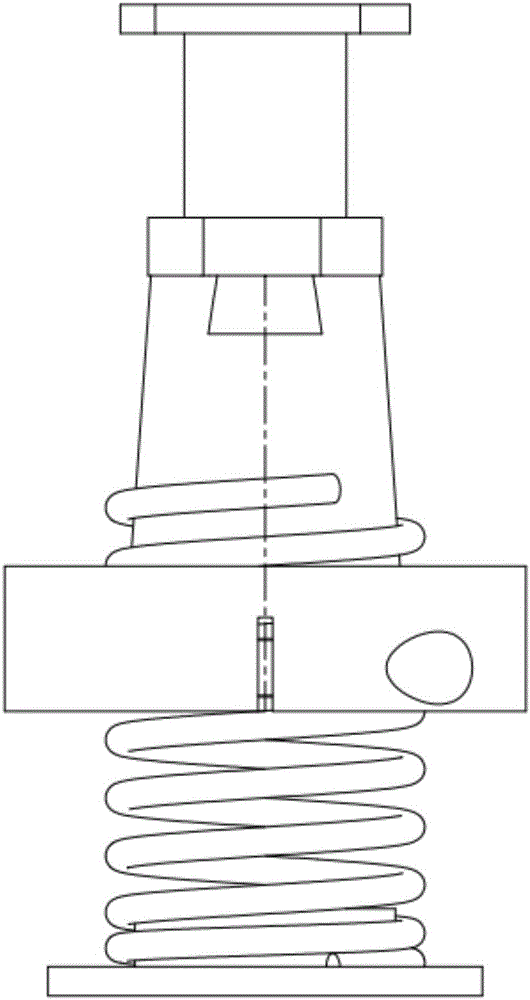
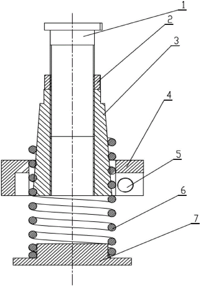
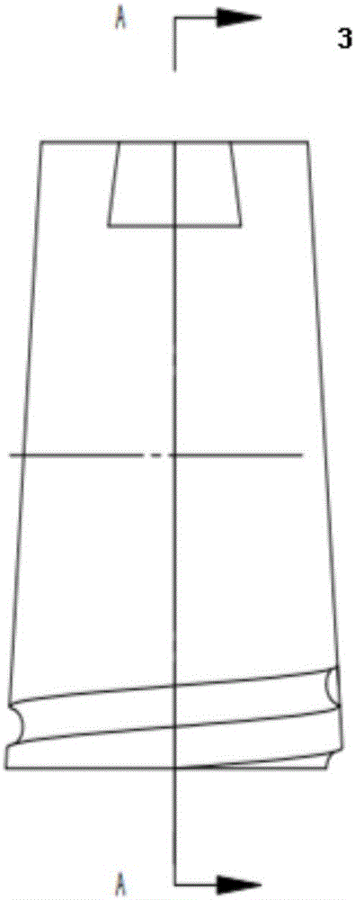
[0029] see Figure 1 to Figure 4 The spring mechanism with adjustable stiffness provided by the preferred embodiment of the present invention is an integrated mechanism, and the spring mechanism can be used in most occasions where the stiffness of the spring needs to be adjusted for system debugging.

[0030] The spring mechanism comprises a screw rod 1, a nut 2, an inner cylinder 3, an outer c...


PUM


Abstract

The invention belongs to the related technical field of elastic structures, and discloses a rigidity-adjustable spring mechanism. The rigidity-adjustable spring mechanism comprises a screw rod, an inner barrel, an outer barrel, a spring and a base, wherein external threads are formed on the screw rod; a threaded hole is formed in the inner barrel and screwed with external threads of the screw rod, so that the screw rod and the inner barrel are in threaded connection; the screw rod rotates to adjust the distance between the screw rod and the base; a spiral groove is formed in the outer wall of the end, facing the base, of the inner barrel; the spiral groove and the spring form a spiral pair; the inner barrel rotates relative to the spring to change the working length of the spring so as to further adjust the rigidity of the spring; the other end of the spring is connected to the base; and the outer barrel is arranged outside the spring and the inner barrel in a sleeving manner, and used for clamping the spring and the inner barrel to prevent the spring from slipping off or used for loosening the spring to facilitate rigidity adjustment of the spring.

Description

technical field [0001] The invention belongs to the technical field related to spring structures, and more specifically relates to a spring mechanism with adjustable stiffness. Background technique [0002] The spring can produce large elastic deformation under the action of external force, and is widely used as an elastic element in mechanical equipment, and is used to control the movement of the mechanism or the position of the part, buffer and absorb vibration, store energy, and measure the size of the force. According to the shape of the spring, the spring can be divided into coil spring, ring spring, disc spring, leaf spring and coil spring. Among them, the helical spring is made by winding spring wire. Because it is easy to manufacture, it is widely used. The most commonly used in general machinery is the cylindrical helical spring. [0003] In the actual manufacturing of springs, there will be manufacturing errors, and the stiffness of the final processed springs wil...

Claims


Application Information

Patent Timeline
Patent Type & Authority Applications(China)
IPC IPC(8): F16F7/00F16F1/12
CPCF16F7/00F16F1/121
Inventor 陈学东姜伟陆澄欧阳力
Owner HUAZHONG UNIV OF SCI & TECH
Learn More