Burner of gas cooker

A gas cooker and burner technology, applied in the direction of gas fuel burners, burners, combustion methods, etc., can solve the problems of incomplete combustion of gas, low thermal efficiency and harmful gases, unfavorable three-dimensional supplement of secondary air, etc., to achieve full benefit Stabilize combustion, improve three-dimensional replenishment ability, and expand the effect of three-dimensional replenishment ability

Active Publication Date: 2017-05-31
ZHONGSHAN INSE GROUP
View PDF13 Cites 3 Cited by
  • Summary
  • Abstract
  • Description
  • Claims
  • Application Information

AI Technical Summary

Problems solved by technology

[0004] At present, the existing gas cooker burners are limited by the shape, size and processing technology of the fire cover, and dense fire holes or fire grooves are mostly set on the same plane of the fire cover, which is not conducive to the three-dimensional supplement of secondary air
In addition, the secondary air replenishment of existing gas cookers depends entirely on the flow direction of the secondary air itself. When the burner is provided with fire holes or fire grooves with different heat intensities, secondary air with low heat intensity will appear. Wasteful and insufficient supplementary secondary air at places with high heat intensity, so that the gas cannot be completely burned during the combustion process of the burner, resulting in low thermal efficiency and excessive generation of harmful gases

Method used


Image

  • Burner of gas cooker
  • Burner of gas cooker
  • Burner of gas cooker

Examples


Embodiment Construction

[0030] The features of the present invention and other related features will be further described in detail below in conjunction with the accompanying drawings through embodiments, so as to facilitate the understanding of those skilled in the art:

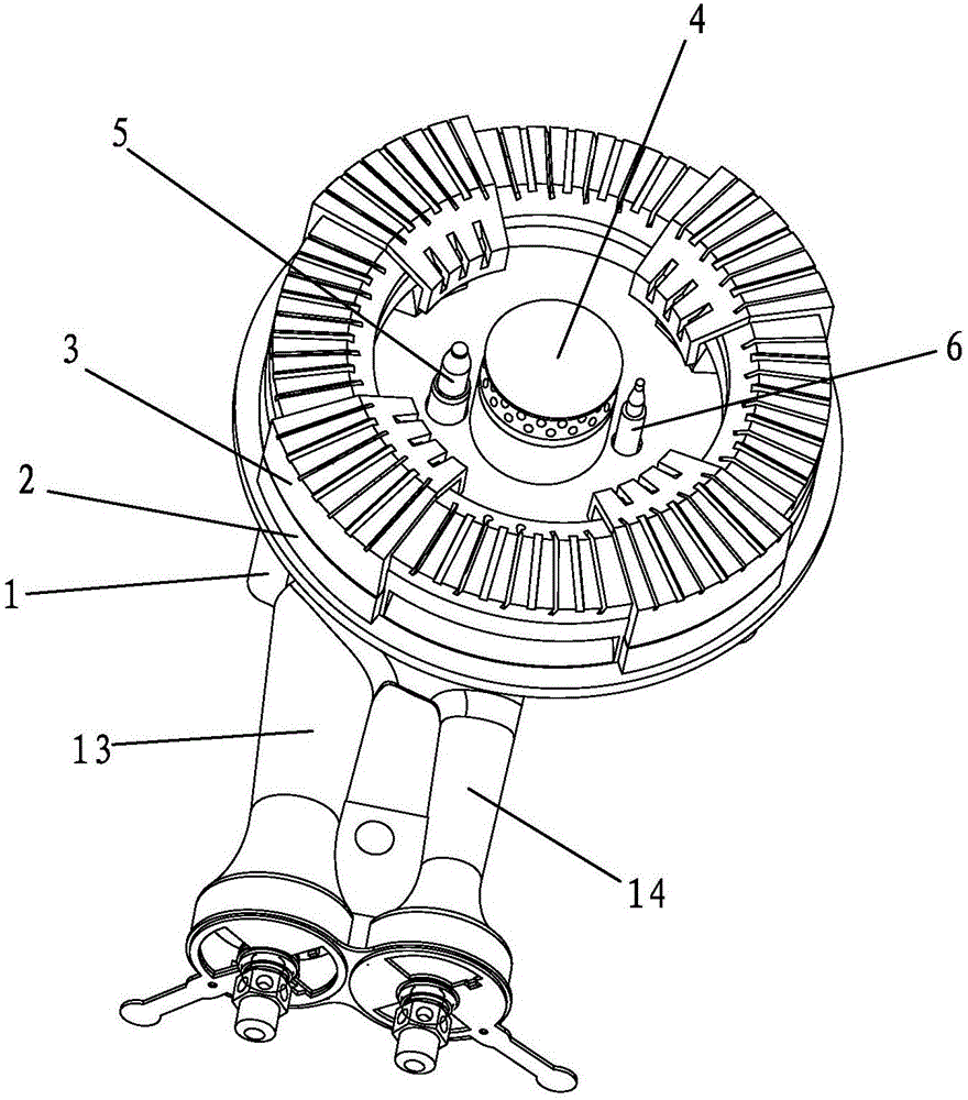
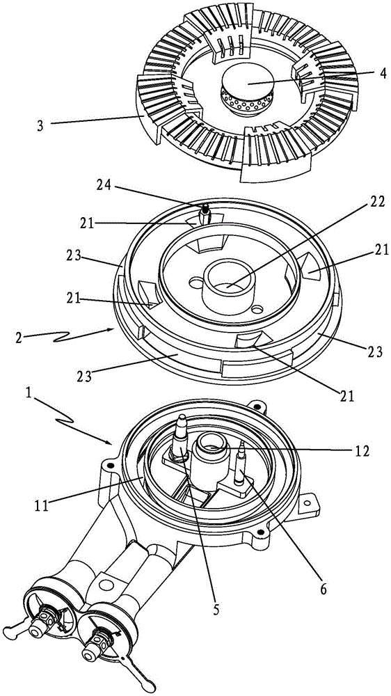
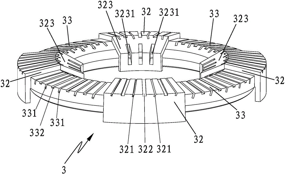
[0031] like Figure 1-5 As shown, a burner of a gas cooker includes a burner 1, and the burner 1 is provided with an outer ring gas groove 11, a central gas groove 12, and an outer ring gas pilot connected to the outer ring gas groove 11. Shooting pipe 13, and the central gas injection pipe 14 that is communicated with described central gas groove 12, described burner head 1 upper end is provided with fire cover seat 2, and described fire cover seat 2 upper end is provided with described outer ring gas groove 11 communicated with the outer ring fire cover 3 and the central fire cover 4 communicated with the central gas tank 12, the lower end of the outer ring fire cover 3 is provided with an annular groove 31 communicated with the ...


PUM


Abstract

The invention discloses a burner of a gas cooker. The burner comprises a burner head, and an outer ring gas groove, a central gas groove, an outer ring gas ejection pipe which communicates with the outer ring gas groove, and a central gas ejection pipe which communicates with the central gas groove are arranged on the burner head; a fire cover seat is arranged at the upper end of the burner head; an outer ring fire cover which communicates with the outer ring gas groove and a central fire cover which communicates with the central gas groove are arranged at the upper end of the fire cover seat; an annular groove which communicates with the outer ring gas groove is formed in the lower end of the outer ring fire cover; a plurality of bosses are arrayed on the circumference of the upper end of the outer ring fire cover; grooves are formed between the adjacent bosses; a plurality of first strip-shaped fire grooves which penetrate through the space in the direction from the ring outer sides to ring core sides of the bosses are formed in the upper surfaces of the bosses; a plurality of second strip-shaped fire grooves which penetrate through the space in the direction from the ring outer sides to ring core sides of the grooves are formed in the upper surfaces of the grooves; and the bottoms of the first strip-shaped fire grooves and the bottoms of the second first strip-shaped fire grooves communicate with the annular groove. According to the burner, the three-dimensional supplementation capability of secondary air is high, and stable combustion is facilitated.

Description

[0001] [technical field] [0002] The invention relates to a burner for a gas stove. [0003] [Background technique] [0004] At present, the existing gas cooker burners are limited by the shape, size and processing technology of the fire cover, and dense fire holes or fire grooves are usually arranged on the same plane of the fire cover, which is not conducive to the three-dimensional supplement of secondary air. In addition, the secondary air replenishment of existing gas cookers depends entirely on the flow direction of the secondary air itself. When the burner is provided with fire holes or fire grooves with different heat intensities, secondary air with low heat intensity will appear. Wasteful and insufficient supplementary secondary air at places with high thermal intensity, so that the gas cannot be completely burned during the combustion process of the burner, resulting in low thermal efficiency and excessive generation of harmful gases. [0005] Therefore, how to over...

Claims


Application Information

Patent Timeline
Patent Type & Authority Applications(China)
IPC IPC(8): F23D14/26F23D14/46F23L9/00F24C3/08F24C15/10
CPCF23D14/26F23D14/46F23L9/00F24C3/085F24C15/10Y02B40/00
Inventor 林天峰邓祥钟万忠刘钧
Owner ZHONGSHAN INSE GROUP
Why Eureka
Try Eureka