Feeding semi-pyrolysis device and method for household waste incineration boiler

A domestic waste incineration and feeding technology, applied in the direction of combustion methods, incinerators, combustion types, etc., can solve the problems of large differences in combustion characteristics of waste components, chemical and physical incomplete combustion losses, and large fluctuations in excess air coefficients. , to achieve the effects of reducing the amount of dioxin produced, overcoming combustion instability, stable combustion and sufficient

Pending Publication Date: 2019-07-02
SHANGHAI ELECTROMECHANICAL DESIGN & RES INST CO LTD
View PDF0 Cites 0 Cited by
  • Summary
  • Abstract
  • Description
  • Claims
  • Application Information

AI Technical Summary

Problems solved by technology

Due to the complex composition of domestic waste and the large differences in combustion characteristics of waste components, in the actual operation process, boiler combustion is unstable, excess air coefficient fluctuates greatly, CO cannot be effectively burned out, and chemical and physical incomplete combustion losses are too large, etc. question

Method used


Image

  • Feeding semi-pyrolysis device and method for household waste incineration boiler
  • Feeding semi-pyrolysis device and method for household waste incineration boiler

Examples


Embodiment Construction

[0019] The present invention will be further described below in conjunction with the accompanying drawings and specific embodiments.

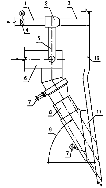
[0020] see figure 1 , a domestic waste incineration boiler feeding semi-pyrolysis device, comprising: a furnace front feeding part and a semi-pyrolysis part. The feeding parts in front of the furnace include: a screw feeder 6, a feeding chute 8, a furnace wall 10, the head of the screw feeder 6 is connected to the feeding chute 8, and the feeding chute 8 has a clamp with the horizontal plane. The angle of the angle is connected to the furnace wall 10 and enters the furnace, and the included angle is the slide pipe angle 9. The chute angle 9 can be set according to the characteristics of the material for the convenience of garbage materials falling into the furnace. The material-pulling air duct 7 on the existing feeding chute 8 needs to be canceled or blocked and out of service. The material is heated by the high-temperature flue gas extract...


PUM


Abstract

The invention relates to a feeding semi-pyrolysis device and method for a household waste incineration circulating fluidized bedboiler. The feeding semi-pyrolysis device for the household waste incineration boiler comprises a boiler front feeding part and a semi-pyrolysis part. The head of a screw feeder (6) of the boiler front feeding part is connected with a feeding chute (8), and the feeding chute is connected into a boiler wall (10) to enter a boiler furnace in the mode of forming an included angle between the feeding chute and the horizontal plane. The included angle refers to a chute angle (9). The semi-pyrolysis part comprises a hot air duct (1), an air evacuating device (2), a boiler-in pipeline (3) and an air evacuating pipeline (5). The air evacuating device is installed betweenthe hot air duct and the boiler-in pipeline. Boiler hot air is connected into the hot air duct. The boiler-in pipeline enters a boiler furnace lean-phase zone through a boiler wall opened hole. One end of the air evacuating pipeline is connected with the air evacuating device, and the other end of the air evacuating pipeline is connected with the head of the screw feeder. A ventilation door (4) isinstalled on the hot air duct in front of the air evacuating device. According to the feeding semi-pyrolysis device for the household waste incineration boiler, materials can be burnt more stably andsufficiently in the waste circulating fluidized bedboiler and exhausting standards are met.

Description

technical field [0001] The invention relates to a feeding system for a garbage incineration circulating fluidized bed boiler, in particular to a feed semi-pyrolysis device and method for a household garbage incineration boiler. Background technique [0002] Domestic waste incineration power generation is an ideal disposal method for reducing the volume and volume of domestic waste and reducing environmental pollution. The incineration technologies widely used at home and abroad mainly include circulating fluidized bed and grate furnace. The circulating fluidized bed boiler has a high fluidization velocity, and the hot air brings a large amount of material to the upper part of the furnace for combustion. The material fills the entire furnace, and the boiler has a large heat capacity. Domestic waste with high and low calorific value. The air in the circulating fluidized bed boiler has sufficient contact with the material, and has the advantages of good incineration performanc...

Claims


Application Information

Patent Timeline
Patent Type & Authority Applications(China)
IPC IPC(8): F23G5/04F23G5/027F23G5/44F23G5/46F23G5/50
CPCF23G5/027F23G5/04F23G5/444F23G5/46F23G5/50F23G2201/10F23G2201/30F23G2202/10F23G2203/50F23G2205/121F23G2206/10
Inventor 顾治强邵嫩飞史敏雍士玮程国杰惠文博杨岳青
Owner SHANGHAI ELECTROMECHANICAL DESIGN & RES INST CO LTD
Why Eureka
Try Eureka