S-shaped regenerative chamber type regenerative burner nozzle

A regenerator, regenerative technology, applied in the direction of burner, combustion method, combustion type, etc., can solve the problems of difficult maintenance, large volume, complex burner structure, etc.

Inactive Publication Date: 2015-07-22
UNIV OF JINAN
View PDF5 Cites 0 Cited by
  • Summary
  • Abstract
  • Description
  • Claims
  • Application Information

AI Technical Summary

Problems solved by technology

Among the existing regenerative burners, the burners with high combustion efficiency generally have a complex structure and a l

Method used


Image

  • S-shaped regenerative chamber type regenerative burner nozzle
  • S-shaped regenerative chamber type regenerative burner nozzle

Examples


Embodiment Construction

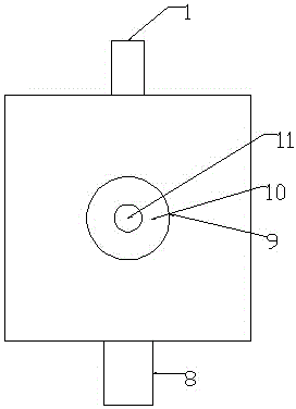
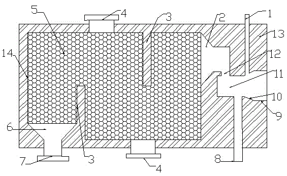
[0009] The regenerative burner adopts integral casting and is divided into a burner body 13 and a regenerator 14 . Such as figure 1 and figure 2 As shown, the burner body 13 is divided into an injection section 9 , a combustion section 10 and a mixing section 11 . The injection section 9 adopts a cylindrical shape, and the combustion section 10 adopts a fan shape, and is connected with the guide burner 1, which is helpful for the dispersion of the mixed gas and enhances the combustion effect. The mixing section 11 adopts a cylindrical shape and connects the air passage 12 and the fuel pipe 8 , and the other side of the air passage 12 adopts a fan-shaped end 2 . The fuel pipe 8 can form any angle with the central axis of the burner. The regenerator 14 is in the shape of a quadrangular prism, and partition plates 3 are arranged alternately up and down to separate the regenerator into an S-shape. The number of partition plates 3 is 1 to 5. If the number is too large, the gas ...


PUM


Abstract

The invention discloses a regenerative burner nozzle and relates to the technical field of burning of heating furnaces, quenching furnaces, forging furnaces, casting ladle preheating devices and heat treatment furnaces. The regenerative burner nozzle is formed in an integral casting mode and divided into a burner nozzle body 13 and a regenerative chamber 14. The burner nozzle body 13 is divided into a spraying segment 9, a burning segment 10 and a mixing segment 11, wherein the spraying segment 9 is cylindrical, the burning segment 10 is in the shape of a sector and is connected with a guiding burner nozzle body 1, dispersion of mixed gas is facilitated, and the burning effect is enhanced. The mixing segment 11 is cylindrical and is connected with an air channel 12 and a fuel pipe 8, and a sector-shaped end 2 is adopted on the other side of the air channel 12. Any angle can be formed between the fuel pipe 8 and the central axis of the burner nozzle. The regenerative chamber 14 is in the shape of a quadrangular prism, partition plates 3 are arranged in a vertical alternating mode so that the regenerative chamber can be partitioned to be in the shape of S, the number of the partition plates 3 ranges from 1 to 5, gas resistance can be increased if the number of the partition plates 3 is too large, and accordingly, gas flowing speed will be reduced. The regenerative chamber 14 is filled with heat accumulation mediums 5, the upper face and the lower face of the regenerative chamber 14 are provided with a heat accumulation medium outlet/inlet 4, and installation and maintenance are facilitated. The side, the tail of which is close to the partition plates 3, of the regenerative chamber 14 is provided with an air pipe port 7, a sector-shaped segment 6 is arranged on the inner side of the air pipe port 7, and gas can be dispersed evenly.

Description

technical field [0001] The invention belongs to the technical field of combustion on heating furnaces, quenching furnaces, forging furnaces, ladle preheating devices and heat treatment furnaces. It particularly relates to a regenerative burner. Background technique [0002] The regenerative burner is a burner device in which two burners with heat storage medium are paired to alternately let gas in the furnace and combustion air flow in, and use high-temperature air to recover waste heat and realize an alternate combustion method to improve combustion efficiency. . The advantage of the regenerative burner is to use the heat of the flue gas to preheat the gas in the burner, thereby improving combustion efficiency, reducing fuel consumption and saving energy. This requires that the regenerative burner should have good heat storage capacity. The heat storage of the regenerative burner is realized through the heat storage medium in the heat storage chamber. Only when the flue ...

Claims


Application Information

Patent Timeline
IPC IPC(8): F23D14/22F23D14/66F23D14/48
CPCF23D14/22F23D14/48F23D14/66Y02E20/34
Inventor 王响刘永杰孙杰璟
Owner UNIV OF JINAN
Why Eureka
Try Eureka