Application method of machine room dehumidifying mechanism

A technology for a computer room and a casing, applied in the field of dehumidifiers, can solve the problems affecting the normal operation of electrical equipment in the computer room, the erosion and oxidation of the humid air of the heat exchanger, and the damage of the heat exchanger, so as to achieve continuous and stable dehumidification performance, improve dehumidification efficiency, The effect of reducing the workload

Inactive Publication Date: 2017-05-31
重庆靠岸机电设备有限公司
View PDF0 Cites 4 Cited by
  • Summary
  • Abstract
  • Description
  • Claims
  • Application Information

AI Technical Summary

Problems solved by technology

In the traditional dehumidifier, due to the high content of water vapor in the working environment, the heat exchanger is easily eroded and oxidized by the humid air when exchanging heat with the air, which in turn causes damage to the heat exchanger and affects the normal operation of the electrical equipment in the machine room. Work

Method used


Image

  • Application method of machine room dehumidifying mechanism
  • Application method of machine room dehumidifying mechanism

Examples


Embodiment 1

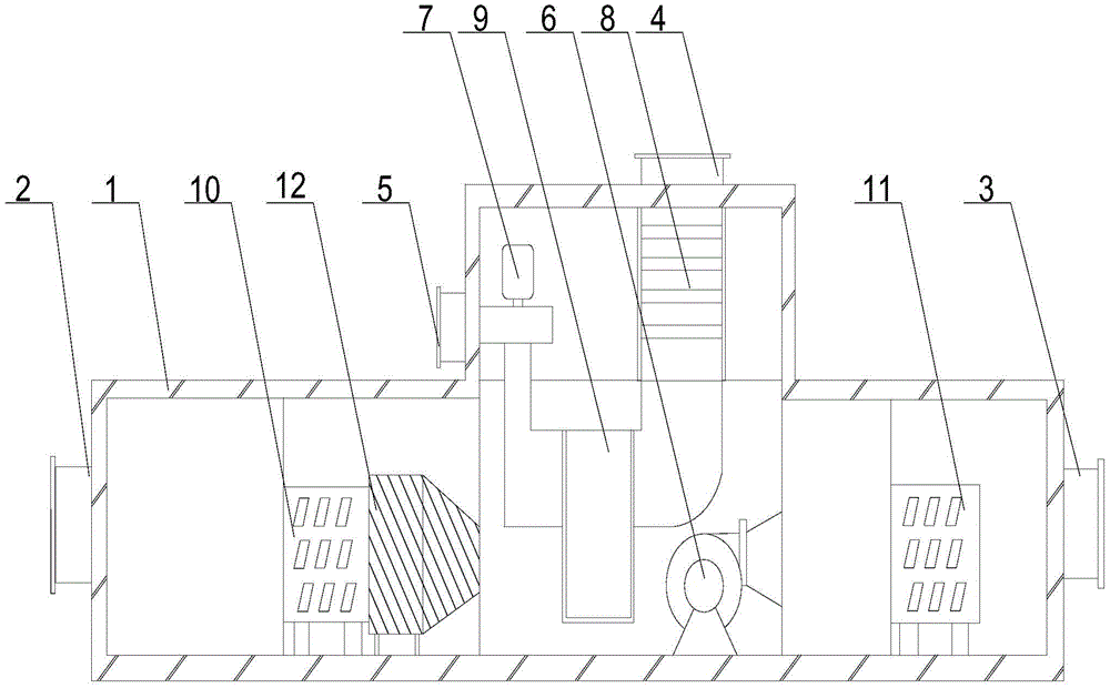
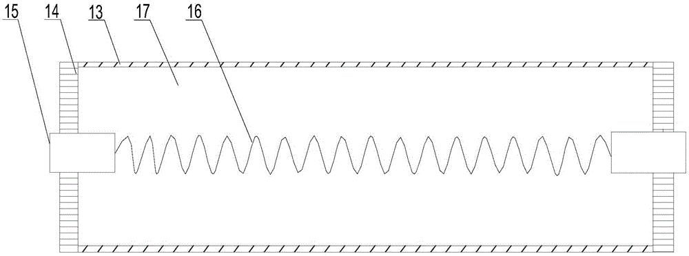
[0024] Such as figure 1 with figure 2 Shown, the present invention comprises the following steps:

[0025] A The cold air in the operating room enters the dehumidification wheel through the air inlet;

[0026] B The front cooler processes the indoor air in the first step, and the treated air enters the funnel-shaped water retaining pan. Since the outer diameter of the water retaining plate decreases along the direction of air flow, a small amount of water vapor in the passing air Coagulate on the inner wall of the disk, and the condensed water droplets are discharged into the casing through the annular groove;

[0027] C The humid air in the operating room is processed in the treatment area, the dehumidification wheel is driven to rotate slowly, and the saturated water vapor in the treatment area enters the regeneration area;

[0028] D Inject fresh air through the regenerative air inlet, and the heater will heat the fresh air;

[0029] E Finally, the dry air is discharge...

Embodiment 2

[0034] Such as figure 1 As shown, in this embodiment, on the basis of Embodiment 1, a front cooler 10 and a rear cooler 12 are installed in the casing 1, the front cooler 10 is arranged on the air inlet 2, and the rear cooler 12 Set on the air outlet 3. The air humidity in the operation room of the machine room is relatively high. Before passing through the dehumidification rotor 9, the air is pretreated by the front cooler 10 to reduce the water vapor content in the air, and at the same time improve the working efficiency of the dehumidification rotor 9. When the air passes through the dehumidification rotor After the wheel 9, a small amount of water vapor remaining in the air is cleaned up by the after cooler 12 to ensure that the air that flows back into the operating room is dry and improves a stable working environment for electrical equipment; the present invention adopts three-stage dehumidification means to ensure the best air dehumidification effect every time.


PUM


Abstract

The invention discloses an application method of a machine room dehumidifying mechanism. The application method comprises the following steps: cold air in an operation room enters a dehumidifying rotating wheel by an intake port; a front cooler performs primary treatment for indoor air, the treated air enters a water stop disc, less water vapor in the air is condensed on the inner wall of the water stop disc, and condensed water drops are discharged into a shell by an annular groove; wet air in the operation room is treated in a treatment area, the dehumidifying rotating wheel is driven to slowly rotate, and the water vapor to be saturated in the treatment area enters a regeneration area; fresh air is injected through a regeneration intake port, and is heated by a heater; and finally, the dried air is exhausted out of the shell to renewedly flow into the operation room.

Description

technical field [0001] The invention relates to a dehumidifier, in particular to a method for using a dehumidification mechanism in a machine room. Background technique [0002] All kinds of electrical equipment in the motor room have high requirements on the environment, so dehumidification equipment is required in the machine room. The dehumidifier is composed of a compressor, heat exchanger, fan, water tank, casing and controller. Its working principle is: the fan draws humid air into the machine and passes through the heat exchanger. At this time, the moisture in the air condenses. It turns into water droplets, turns into dry air and is discharged outside the machine. This cycle reduces the indoor humidity. In the traditional dehumidifier, due to the high content of water vapor in the working environment, the heat exchanger is easily eroded and oxidized by the humid air when exchanging heat with the air, which in turn causes damage to the heat exchanger and affects the ...

Claims


Application Information

Patent Timeline
Patent Type & Authority Applications(China)
IPC IPC(8): F24F3/14
CPCF24F3/1423F24F2003/1464
Inventor 陈启友
Owner 重庆靠岸机电设备有限公司
Why Eureka
Try Eureka