Application method of dehumidifying system of power supply machine room

A technology for power supply room and cabinet, applied in air-conditioning systems, separation methods, chemical instruments and methods, etc., can solve the problems of erosion and oxidation of the humid air of the heat exchanger, affecting the normal operation of the electrical equipment in the machine room, and damage to the heat exchanger, etc. Achieve the effect of improving dehumidification efficiency, continuous and stable dehumidification performance, and reducing workload

Inactive Publication Date: 2017-05-31
重庆靠岸机电设备有限公司
View PDF0 Cites 0 Cited by
  • Summary
  • Abstract
  • Description
  • Claims
  • Application Information

AI Technical Summary

Problems solved by technology

In the traditional dehumidifier, due to the high content of water vapor in the working environment, the heat exchanger is easily eroded and oxidized by the humid air when exchanging heat with the air, which in turn causes damage to the heat exchanger and affects the normal operation of the electrical equipment in the machine room. Work

Method used


Image

  • Application method of dehumidifying system of power supply machine room
  • Application method of dehumidifying system of power supply machine room

Examples


Embodiment 1

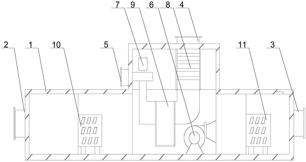
[0025] Such as figure 1 and figure 2 Shown, the present invention comprises the following steps:

[0026] The cold air in the A operating room enters the dehumidification wheel through the air inlet;

[0027] The humid air in the operating room B is processed in the treatment area, the dehumidification wheel is driven to rotate slowly, and the saturated water vapor in the treatment area enters the regeneration area;

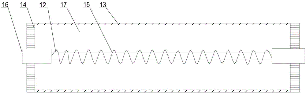
[0028] C injects fresh air through the regenerative air inlet, and the heater heats the fresh air;

[0029] The aluminum rod in the D heater can play a temporary repair function when the heating wire is damaged, ensuring that the heating wire continues to work within a certain period of time;

[0030] E Finally, the dry air is discharged from the casing and re-flows into the operating room;

[0031] The above steps include a casing 1, on which the casing 1 is provided with an air inlet 2, an air outlet 3, a regenerative air inlet 4 and a regenerative air out...

Embodiment 2

[0034] Such as figure 1 As shown, in this embodiment, on the basis of Embodiment 1, a front cooler 10 and a rear cooler 12 are installed in the casing 1, the front cooler 10 is arranged on the air inlet 2, and the rear cooler 12 Set on the air outlet 3. The air humidity in the operating room of the substation is relatively high. Before passing through the dehumidification rotor 9, the air is pretreated by the front cooler 10 to reduce the water vapor content in the air, and at the same time improve the working efficiency of the dehumidification rotor 9. When the air passes through the dehumidification rotor After the wheel 9, a small amount of water vapor remaining in the air is cleaned through the aftercooler 12 to ensure that the air that flows back into the operating room is dry and improves a stable working environment for electrical equipment; the present invention adopts three-stage dehumidification means to ensure the best air dehumidification effect every time.


PUM


Abstract

The invention discloses an application method of a dehumidifying system of a power supply machine room. The method comprises the following steps that cold air in an operation chamber passes through an air inlet and enters a dehumidification runner; wet air in the operation chamber is treated in a treatment area, the dehumidification runner is driven to slowly rotate, and moisture tending to be saturated in the treatment area enters a regeneration area; fresh air is injected through a regeneration air inlet, and a heater heats the fresh air; an aluminum bar in the heater can play a temporary repairing role when an electric heating wire is damaged, and it is guaranteed that the electric heating wire continuously works within a certain period; and finally, the dried air is discharged out of a machine shell and flows into the operation chamber again.

Description

technical field [0001] The invention relates to a dehumidifier, in particular to a method for using a dehumidification system in a power supply machine room. Background technique [0002] All kinds of electrical equipment in the motor room have high requirements on the environment, so dehumidification equipment is required in the machine room. The dehumidifier is composed of a compressor, heat exchanger, fan, water tank, casing and controller. Its working principle is: the fan draws humid air into the machine and passes through the heat exchanger. At this time, the moisture in the air condenses. It turns into water droplets, turns into dry air and is discharged outside the machine. This cycle reduces the indoor humidity. In the traditional dehumidifier, due to the high content of water vapor in the working environment, the heat exchanger is easily eroded and oxidized by the humid air when exchanging heat with the air, which in turn causes damage to the heat exchanger and af...

Claims


Application Information

Patent Timeline
Patent Type & Authority Applications(China)
IPC IPC(8): F24F3/14B01D53/06B01D53/26
CPCF24F3/1423B01D53/06
Inventor 陈启友
Owner 重庆靠岸机电设备有限公司
Why Eureka
Try Eureka