Air treatment system for machine room of hydropower station

A technology for air handling systems and hydropower stations, which is used in air conditioning systems, space heating and ventilation, and household heating, etc. It can solve the problem of erosion and oxidation of humid air in heat exchangers, damage to heat exchangers, and affecting the normal operation of electrical equipment in computer rooms, etc. problems, to achieve the effect of improving work stability, uniform heating, and long service life

Inactive Publication Date: 2017-05-31
重庆靠岸机电设备有限公司
View PDF0 Cites 0 Cited by
  • Summary
  • Abstract
  • Description
  • Claims
  • Application Information

AI Technical Summary

Problems solved by technology

In the traditional dehumidifier, due to the high content of water vapor in the working environment, the heat exchanger is easily eroded and oxidized by the humid air when exchanging heat with the air, which in turn causes damage to the heat exchanger and affects the normal operation of the electrical equipment in the machine room. Work

Method used


Image

  • Air treatment system for machine room of hydropower station
  • Air treatment system for machine room of hydropower station
  • Air treatment system for machine room of hydropower station

Examples


Embodiment 1

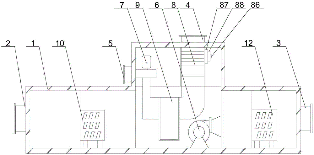
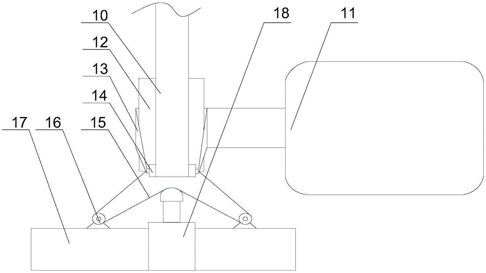
[0024] like figure 1 , figure 2 and Figure 5 As shown, the air treatment system of a hydroelectric power station machine room according to the present invention includes a casing 1, on which an air inlet 2, an air outlet 3, a regenerative air inlet 4 and a regenerative air outlet 5 are arranged, and the casing 1 1 is equipped with a fan 6, a heater 8, a dehumidification wheel 9 and a regeneration fan 7, one end of the fan 6 is connected to the air inlet 2, the other end of the fan 6 is connected to the air outlet 3, and the heater 8 is connected to the air outlet 3 respectively. The regeneration air inlet 4, the dehumidification runner 9 and the regeneration blower 7 are connected in sequence, and the other end of the regeneration blower 7 is connected with the regeneration outlet 5, and a pulley 12 is installed on the output end of the motor 11, and also includes a pulley 12 The roller 14 arranged tangentially, the pulley 12, the roller 14 and the dehumidification runner ...

Embodiment 2

[0028] like image 3 As shown, this embodiment is based on Embodiment 1, the connecting rod 13 is an elastic plastic rod, and the two ends of the elastic plastic rod are sleeved on the rotating shafts of the pulley 12 and the roller 14 respectively. In order to prevent the roller 14 from moving with the belt 10 when rotating, the connecting rod 13 connects the pulley 12 to the roller 14. When the roller 14 is pulled at the output end of the cylinder 18, the connecting rod 13 made of elastic plastic material will produce a small deformation to The movement of the rollers 14 is accommodated while ensuring favorable support of the rollers 14 .

Embodiment 3

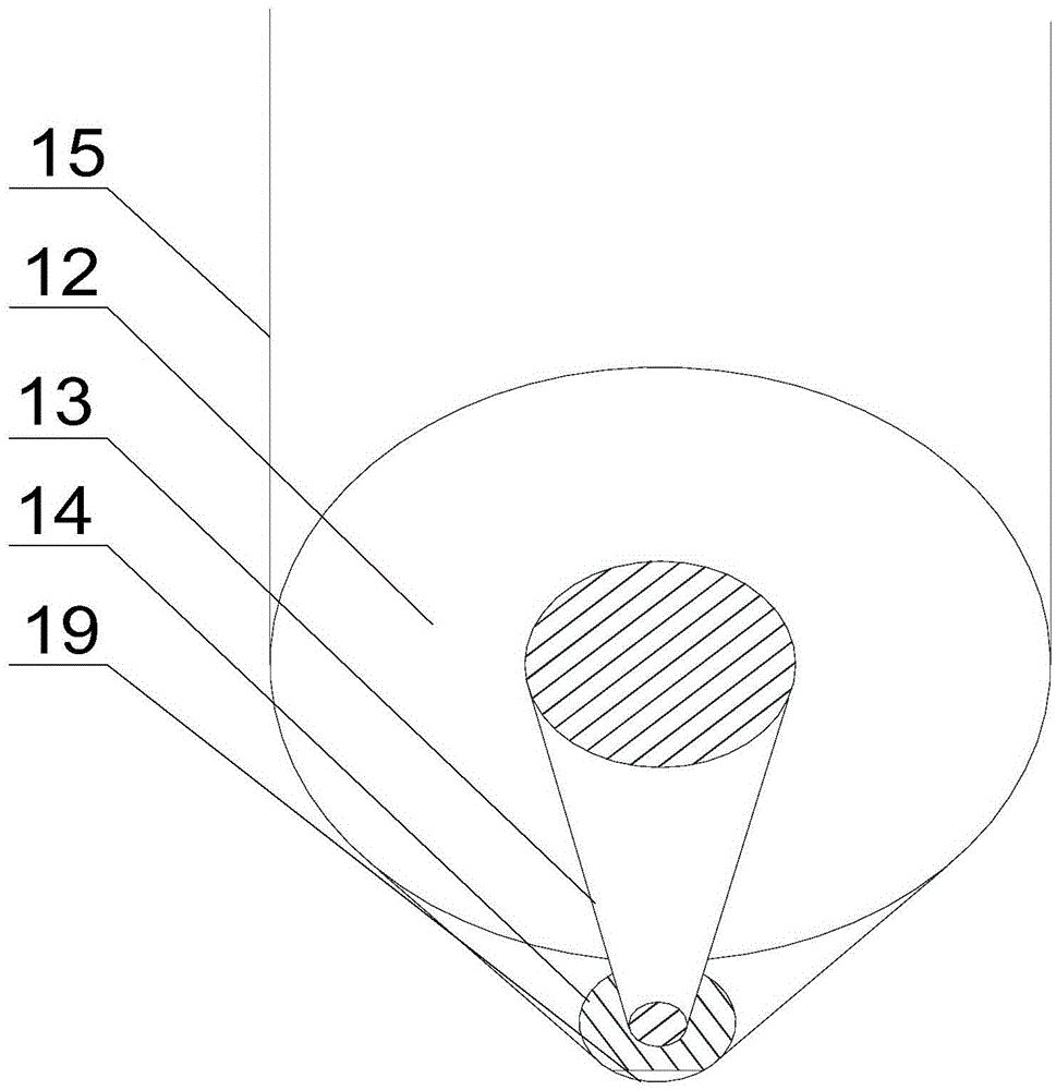
[0030] like Figure 4 As shown, in this embodiment, on the basis of Embodiment 1, one end of the connecting rod 13 is provided with a through hole, the rotating shaft of the pulley 12 is in clearance fit with the through hole, and the other end of the connecting rod 13 is hinged with the rotating shaft of the roller 14. As preferably, a through hole is provided at one end of the connecting rod 13, and the rotating shaft of the pulley 12 fits in clearance with the through hole.


PUM


Abstract

The invention discloses an air treatment system for a machine room of a hydropower station. The air treatment system comprises a machine shell, and further comprises a rolling wheel which is arranged tangent with a belt wheel; an air inlet, an air outlet, a regeneration air inlet and a regeneration air outlet are formed in the machine shell; a fan, a heater, a dehumidifying rotating wheel and a regeneration fan are installed in the machine shell; the belt wheel is arranged on the output end of a motor; a pressure sensors is arranged at the tangent position of the rolling wheel and a belt; an air cylinder and a plurality of fixed pulleys are installed on a support; the multiple fixed pulleys are symmetrically arranged on two sides of the output end of the air cylinder; and two ends of a rotating shaft of the rolling wheel are connected with a traction line, and the traction line is wound around the fixed pulleys and the output end of the air cylinder to form a pulley block. According to the air treatment system for the machine room of the hydropower station, the output end of the air cylinder extends forwards so as to pull the rotating shaft of the rolling wheel so that the tension of the belt can be restored again, the normal rotation of the dehumidifying rotating wheel and the belt wheel can be guaranteed, and therefore water vapor in an operation room of the hydropower station can be conveniently and quickly removed, meanwhile, the connection stability of the dehumidifying rotating wheel and the motor can be improved, and the dehumidifying efficiency of the dehumidifying rotating wheel can be ensured.

Description

technical field [0001] The invention relates to a dehumidifier, in particular to an air treatment system for a machine room of a hydropower station. Background technique [0002] All kinds of electrical equipment in the motor room have high requirements on the environment, so dehumidification equipment is required in the machine room. The dehumidifier is composed of a compressor, heat exchanger, fan, water tank, casing and controller. Its working principle is: the fan draws humid air into the machine and passes through the heat exchanger. At this time, the moisture in the air condenses. It turns into water droplets, turns into dry air and is discharged outside the machine. This cycle reduces the indoor humidity. In the traditional dehumidifier, due to the high content of water vapor in the working environment, the heat exchanger is easily eroded and oxidized by the humid air when exchanging heat with the air, which in turn causes damage to the heat exchanger and affects the...

Claims


Application Information

Patent Timeline
Patent Type & Authority Applications(China)
IPC IPC(8): F24F3/147
CPCF24F3/14F24F3/147F24F2003/1464
Inventor 陈启友
Owner 重庆靠岸机电设备有限公司
Why Eureka
Try Eureka