
Heat storage components and air conditioners

A heat accumulator and air conditioner technology, applied in air conditioning systems, heat storage equipment, indirect heat exchangers, etc., can solve the problems of hot and cold room temperature, affect user comfort, reduce heating effect, etc., and achieve improved Satisfaction, good heating effect, effect of improving user experience

Active Publication Date: 2019-01-22
WUHAN REFRIGERATION EQUIP OF MIDEA GROUP +1
View PDF8 Cites 0 Cited by
  • Summary
  • Abstract
  • Description
  • Claims
  • Application Information

AI Technical Summary

Problems solved by technology

[0002] The air conditioner in the related art usually uses the discharge temperature of the compressor to perform hot air defrosting. When defrosting starts, the four-way valve is reversed so that the outdoor heat exchanger releases heat, and the indoor heat exchanger absorbs heat, resulting in indoor ambient temperature. In this way, in a colder environment, the air conditioner runs a refrigeration cycle, which will cause the room temperature to be hot and cold, affecting the comfort of the user; When the upper part has been defrosted, it must wait until the lower part of the outdoor heat exchanger is completely defrosted to complete the defrosting and enter the normal heating operation state at the same time, so part of the heat is wasted and the defrosting process is prolonged. Reduced heating capacity and reduced overall heating effectiveness

Method used


Image

  • Heat storage components and air conditioners
  • Heat storage components and air conditioners
  • Heat storage components and air conditioners

Examples


Embodiment Construction

[0037] In order to understand the above-mentioned purpose, features and advantages of the present invention more clearly, the present invention will be further described in detail below in conjunction with the accompanying drawings and specific embodiments. It should be noted that, in the case of no conflict, the embodiments of the present application and the features in the embodiments can be combined with each other.

[0038] In the following description, many specific details are set forth in order to fully understand the present invention. However, the present invention can also be implemented in other ways different from those described here. Therefore, the protection scope of the present invention is not limited by the specific details disclosed below. EXAMPLE LIMITATIONS.

[0039] Refer below Figure 1a to Figure 3b A thermal storage assembly and an air conditioner according to some embodiments of the present invention are described.

[0040] like Figure 1a , Figur...


PUM


Abstract

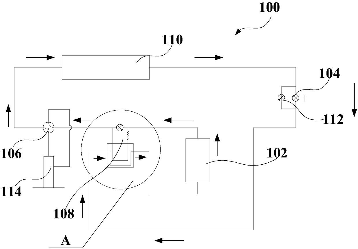
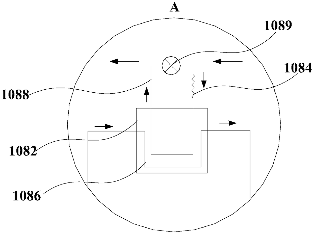
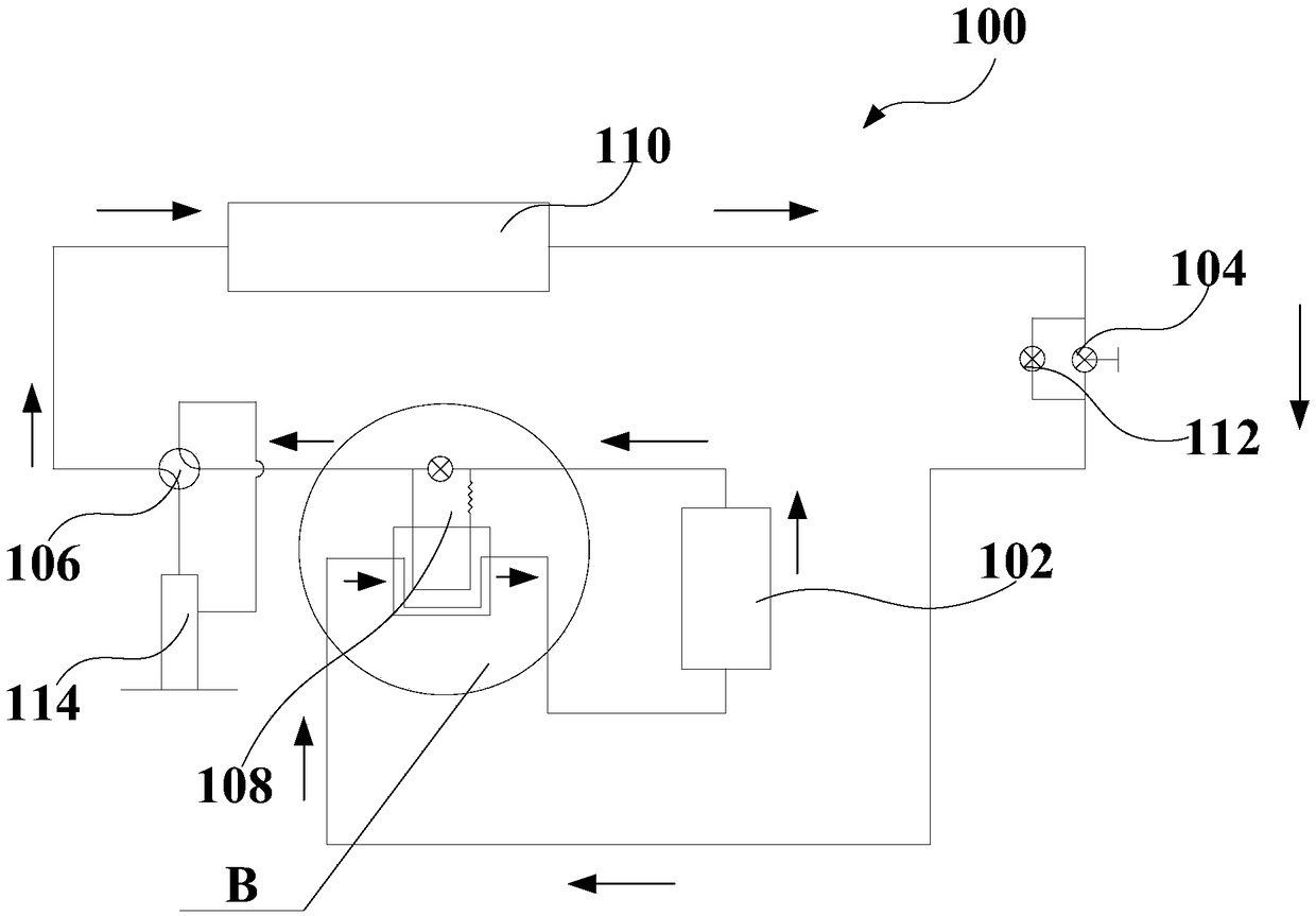
A heat storage assembly (108) and an air conditioner (100), the heat storage assembly (108) comprising: a heat storage device (1082); at least one electric heating member (1084), which is provided on the heat storage device (1082); a first pipeline (1086), which is provided on the heat storage device (1082) and which is in communication with a throttling apparatus (104) and an outdoor heat exchanger (102); a second pipeline (1088), which is provided on the heat storage device (1082) and which is in communication with the outdoor heat exchanger (102) and a four-way valve (106); a first control member (1089), which is provided in parallel with the second pipeline (1088) and which is in communication with the outdoor heat exchanger (102) and the four-way valve (106). By means of controlling the working status of the first control member (1089) and at least one electric heating member (1084), the heat storage assembly (108) may meet the needs of the air conditioner (100) so as to run in different modes; when defrosting in a heating mode, the electric heating member (1084) operates such that the temperature of a refrigerant which flows through the first pipeline (1086) and the second pipeline (1088) increases such that the outdoor heat exchanger (102) defrosts promptly, rapidly and thoroughly, and such that the temperature of the refrigerant and air which flow into the compressor is increased to ensure good defrosting efficiency and stable heating efficiency, thus enhancing the comfort of use and satisfaction of a user.

Description

technical field [0001] The invention relates to the technical field of air conditioners, in particular to a heat storage assembly and an air conditioner. Background technique [0002] The air conditioner in the related art usually uses the discharge temperature of the compressor to perform hot air defrosting. When defrosting starts, the four-way valve is reversed so that the outdoor heat exchanger releases heat, and the indoor heat exchanger absorbs heat, resulting in indoor ambient temperature. In this way, in a colder environment, the air conditioner runs a refrigeration cycle, which will cause the room temperature to be hot and cold, affecting the comfort of the user; When the upper part has been defrosted, it must wait until the lower part of the outdoor heat exchanger is completely defrosted to complete the defrosting and enter the normal heating operation state at the same time, so part of the heat is wasted and the defrosting process is prolonged. Reduced heating cap...

Claims


Application Information

Patent Timeline
Patent Type & Authority Patents(China)
IPC IPC(8): F28D20/00F24F5/00
CPCF24F5/0017F28D20/00F28D2020/0004Y02E60/14
Inventor 谭周衡阮涛刘奇伟
Owner WUHAN REFRIGERATION EQUIP OF MIDEA GROUP
Learn More