Measurement method for azimuth angle test of microwave guide equipment

A technology for guiding equipment and measurement methods, applied in theodolite and other directions, can solve problems such as inability to ensure complete coincidence, large impact on operation, disadvantages, etc., and achieve the effects of simple and fast measurement methods, reducing errors, and shortening test time

Active Publication Date: 2017-05-31
NO 20 RES INST OF CHINA ELECTRONICS TECH GRP
View PDF8 Cites 2 Cited by
  • Summary
  • Abstract
  • Description
  • Claims
  • Application Information

AI Technical Summary

Problems solved by technology

But this method has the following problems: 1) the selection of the angular position is generally to first determine the center line of the antenna array, then select a point on it as the 0° point according to the terrain, and then obtain an antenna array on the ground through this point The projected parallel lines, the rest of the points are obtained by calculating the distance from the 0° point, and then measuring on the parallel lines with a tape measure
This process is also greatly affected by human operations, and there is no guarantee that the two will completely overlap
[0005] It can be seen that the above method will introduce too many errors due to operational factors
At the same time, there is too much work in advance. Once the antenna installation position of the microwave guidance equipment changes, a lot of work needs to be done again
The existence of these problems is very unfavorable to the rapid and accurate measurement

Method used


Image

  • Measurement method for azimuth angle test of microwave guide equipment
  • Measurement method for azimuth angle test of microwave guide equipment
  • Measurement method for azimuth angle test of microwave guide equipment

Examples


Embodiment Construction

[0025] The present invention will be further described below in conjunction with the accompanying drawings and embodiments, and the present invention includes but not limited to the following embodiments.

[0026] The present invention comprises the following steps:

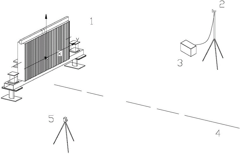
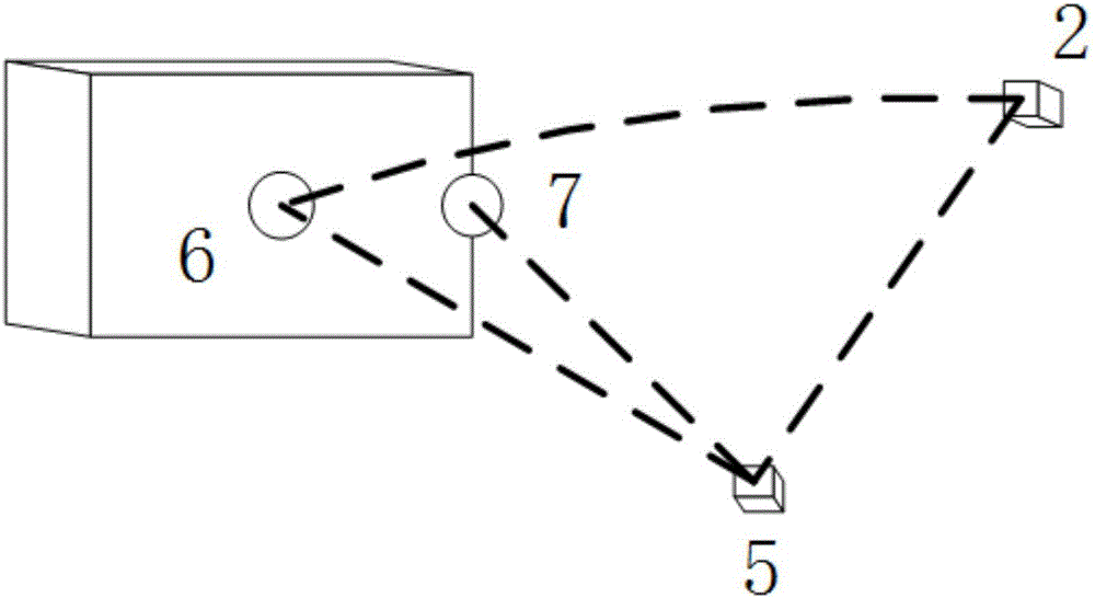
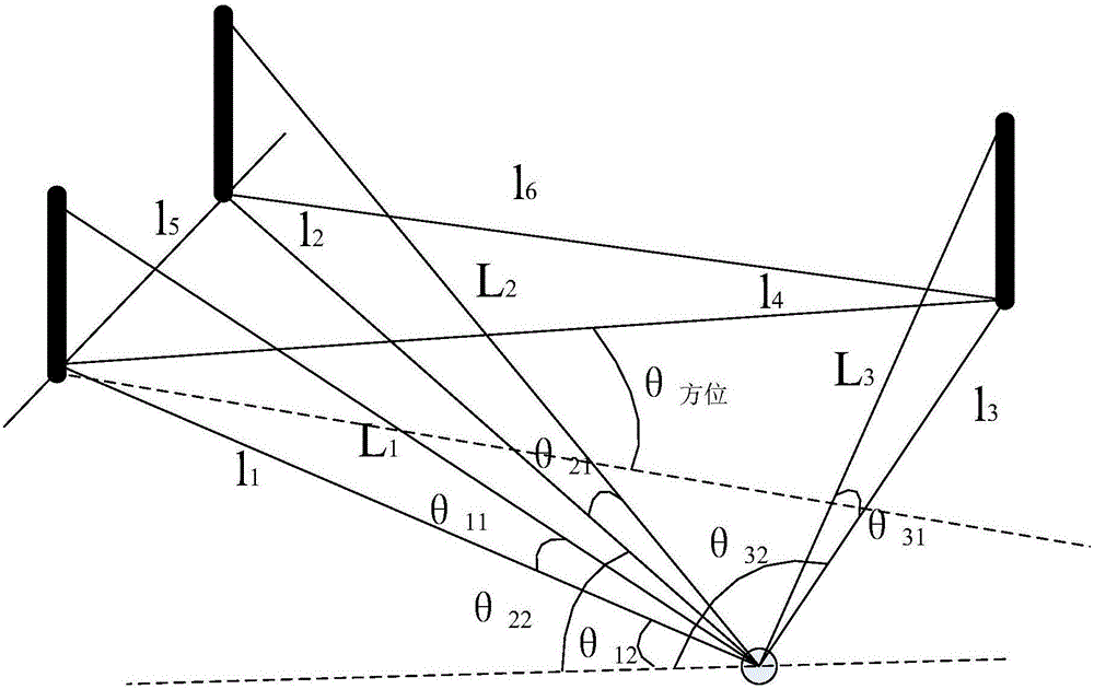
[0027] (1) Arbitrarily select a location within the coverage of the microwave guidance equipment (±40°) to place the dedicated ground angle measurement equipment and the angle measurement test antenna (the two are erected centrally). Then select any position where the antenna of the microwave guidance equipment and the antenna of the angle measurement test can be seen visually to erect the theodolite. Use the theodolite to obtain the following positions: Azimuth Antenna Center (L 1 ,θ 11 ,θ 12 ), any auxiliary point on the azimuth antenna plane (L 2 ,θ 21 ,θ 22 ), the center of the goniometric test antenna (L 3 ,θ 31 ,θ 32 ).

[0028] where L1 is the slant distance from the center point of the azimuth a...


PUM


Abstract

The invention provides a measurement method for an azimuth angle test of microwave guide equipment. The method comprises the steps of arbitrarily selecting a point from a coverage range of the microwave guide equipment and arranging ground-special angle measurement equipment and an angle measurement test antenna; selecting any position at which an azimuth antenna and the angle measurement test antenna of the microwave guide equipment can be watched for arranging a theodolite; obtaining the center of the azimuth antenna, any auxiliary point on the plane of the azimuth antenna and the position of the center of the angle measurement test antenna by using the theodolite; calculating a horizontal angle of the angle measurement test antenna relative to the center of the azimuth antenna; and comparing the horizontal angle with azimuth angle data provided by the ground-special angle measurement equipment for the difference to judge the accuracy of the microwave guide equipment, thereby judging whether the indicator of the microwave guide equipment reaches the standard or not. According to the measurement method, the performance index of the microwave guide equipment can be more accurately and conveniently tested.

Description

technical field [0001] The invention belongs to the technical field of measurement methods, and relates to land-based inspection of microwave guidance equipment, in particular to a method for measuring angles during land-based inspection of microwave guidance equipment. Background technique [0002] Microwave guidance equipment is a kind of aircraft landing / ship guidance equipment, referring to the technical system of the Microwave Landing System (MLS) issued by the International Civil Aviation Organization (ICAO), so that the azimuth antenna and the elevation antenna can transmit stably into the air during work. space scanning beam. The azimuth and elevation scanning beams received by the airborne equipment calculate the relative angle information of the aircraft relative to the scanning antenna, combined with the distance information of the ranging system and the positional relationship between the equipment scanning antenna and the landing / ship point, through the seat of ...

Claims


Application Information

Patent Timeline
Patent Type & Authority Applications(China)
IPC IPC(8): G01C1/02
CPCG01C1/02
Inventor 王冀龙王琳
Owner NO 20 RES INST OF CHINA ELECTRONICS TECH GRP
Why Eureka
Try Eureka