Autocorrection near-infrared diffuse reflectance detection system and method
A detection system and automatic calibration technology, applied in measurement devices, material analysis by optical means, instruments, etc., can solve the problems of low measurement accuracy, waste of time and money, and inability to truly achieve online detection, and achieve near-infrared spectroscopy. Accuracy, improved stability and the effect of measurement accuracy
- Summary
- Abstract
- Description
- Claims
- Application Information
AI Technical Summary
Problems solved by technology
Method used
Image
Examples
Embodiment 1
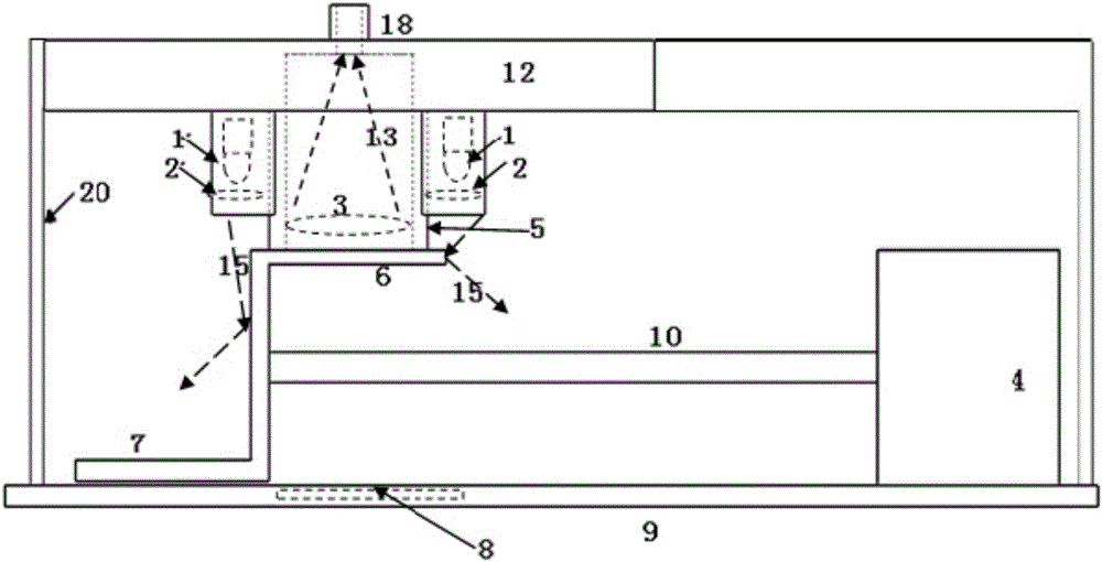
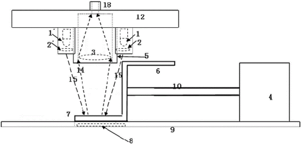
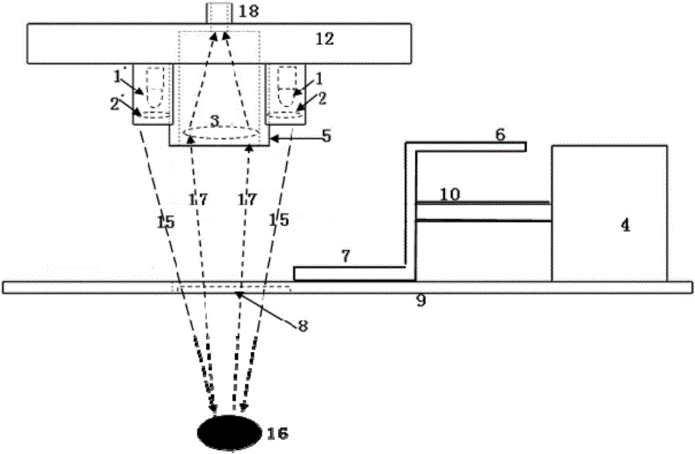
[0041] Such as Figure 1-3 As shown, an automatic correction near-infrared diffuse reflectance detection system includes an optical system, the optical system includes a light source system and a spectrum collection system, the light source system is located around the spectrum collection system, and the spectrum collection system is located directly above the sample to be measured .
[0042] The light source system includes a near-infrared light source 1 and an optical filter 2. The near-infrared light source 1 passes through the optical filter 2 to eliminate unnecessary wave bands. Optimally, the light source system includes multiple light sources, which are evenly distributed around the spectrum collection system, thus reducing the impact of near-infrared light source fluctuations in a single light source system on the process of near-infrared diffuse reflectance detection.
[0043] The spectrum collection system includes a spectrum collection window 5 , an optical collect...
Embodiment 2
[0049]A detection method using an automatic correction near-infrared diffuse reflectance detection system, the system is consistent with the connection mode and working principle described in Embodiment 1.
[0050] The method of using the near-infrared diffuse reflectance detection system of automatic correction, its steps are as follows:
[0051] (1) Start the motor.
[0052] (2) The motor drives the calibration head through the moving shaft to completely block the spectrum collection window 5 by the partition. At this time, the spectrum collection system is completely isolated from the light source, and the background spectrum is collected.
[0053] When the correction head moves to figure 1 position, the partition plate 6 of the correction head is close to the spectrum collection window 5, and the near-infrared light 15 emitted by the light source is blocked from the spectrum collection system, and the background spectrum 13 generated at this time is coupled into the opti...
PUM
 Abstract
Description
Claims
Application Information
 - R&D
- Intellectual Property
- Life Sciences
- Materials
- Tech Scout
- Unparalleled Data Quality
- Higher Quality Content
- 60% Fewer Hallucinations
Browse by: Latest US Patents, China's latest patents, Technical Efficacy Thesaurus, Application Domain, Technology Topic, Popular Technical Reports.
© 2025 PatSnap. All rights reserved.Legal|Privacy policy|Modern Slavery Act Transparency Statement|Sitemap|About US| Contact US: help@patsnap.com


