
A display panel and a liquid crystal display device encapsulated with a quantum dot layer

A display panel and liquid crystal layer technology, applied in instruments, nonlinear optics, optics, etc., can solve problems such as small display viewing angle and color cast of the display panel

Active Publication Date: 2018-11-23
HISENSE VISUAL TECH CO LTD
View PDF6 Cites 0 Cited by
  • Summary
  • Abstract
  • Description
  • Claims
  • Application Information

AI Technical Summary

Problems solved by technology

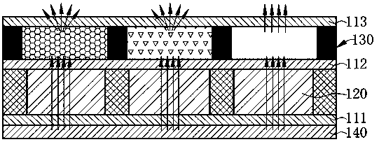
Therefore, the viewing angle of the blue primary color light with a single direction is much smaller than that of the scattered red and green primary color light, which causes the problem of color cast in the display panel under multiple viewing angles.

Method used


Image

  • A display panel and a liquid crystal display device encapsulated with a quantum dot layer
  • A display panel and a liquid crystal display device encapsulated with a quantum dot layer
  • A display panel and a liquid crystal display device encapsulated with a quantum dot layer

Examples


Embodiment 1

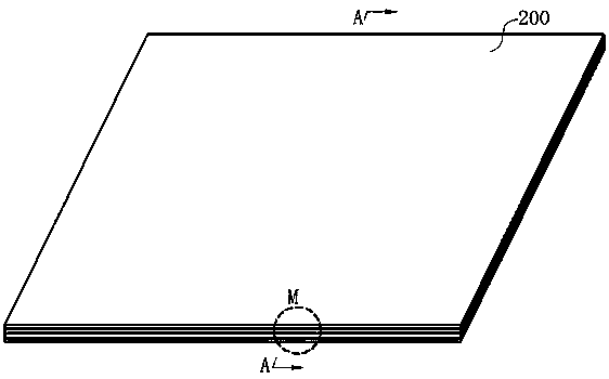
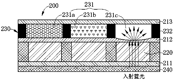
[0037] For a display panel 200 provided in Embodiment 1 of the present invention, please refer to Figure 2a As shown, in order to more clearly express the local structure of the quantum dot display panel 200, along Figure 2a After the cross-section in the middle A direction and the partial zoom-in at M, please refer to Figure 2b As shown, the quantum dot display panel 200 includes: a lower substrate 211 , a middle substrate 212 , an upper substrate 213 , a liquid crystal layer 220 and a quantum dot layer 230 .

[0038]Specifically, the liquid crystal layer 220 is encapsulated between the lower substrate 211 and the middle substrate 212, and the amount of backlight light transmission is controlled by the inversion state of the liquid crystal molecules in the liquid crystal layer 220. The quantum dot layer 230 is arranged above the liquid crystal layer 220 and encapsulated in the middle substrate. 212 and the upper substrate 213, the quantum dot layer 230 includes a pluralit...

Embodiment 2

[0062] For a liquid crystal display device provided by Embodiment 2 of the present invention, please refer to image 3 As shown, the liquid crystal display device 300 includes the display panel 200 provided in the first embodiment above, and further includes: a backlight module 301 arranged under the display panel 200 and used to provide a blue backlight.

[0063]In summary, the application of the present invention provides a display panel and a liquid crystal display device encapsulating a quantum dot layer, wherein, in the provided display panel, the substrate encapsulated in the blue sub-pixel unit is configured in a non-planar shape. When the blue light transmitted by the blue sub-pixel unit passes through the substrate with a non-planar shape, the blue light is emitted from the blue sub-pixel unit at different exit angles and in the form of divergent light, which is different from the excited blue light emitted at different exit angles. Red light and green light together ...


PUM


Abstract

A liquid crystal panel (200) packaged with a quantum dot layer (230) and a liquid crystal display device (300). The liquid crystal panel (200) is configured with several pixel units (231), and each of the pixel units (231) is composed of sub-pixel units in different colors; a liquid crystal layer (220) controls the backlight transmission transmitted to each sub-pixel; sub-pixel units in different colors comprise red sub-pixel units (231a) packaged with quantum dot materials, green sub-pixel units (231b), and blue sub-pixel units (231c) capable of transmitting blue backlight, wherein the surface of a package substrate packaging the pixel unit (231) at the blue sub-pixel units (231c) is configured to be a non-plane shape. When the blue light in the blue sub-pixel units (231c) is configured with a non-planar substrate, the blue light is transmitted in the non-parallel direction, the blue light, the red and green lights obtained by the excitation of the blue light and presenting dispersing lights can commonly realize the color display of the pixel unit (231), thus the color cast of each pixel unit (231) under multiple views can be solved.

Description

technical field [0001] The invention relates to the technical field of liquid crystal display, in particular to a quantum dot display panel and a liquid crystal display device. Background technique [0002] A liquid crystal panel in the prior art includes a liquid crystal layer sealed between two parallel glass substrates, and a color filter placed above the liquid crystal layer. When the liquid crystal panel is used to display the picture, the white light source is used as the backlight, and the switching state of the liquid crystal molecules controlled by the voltage in the liquid crystal layer is used to control the on-off of the backlight light. When the backlight light passing through the liquid crystal layer passes through the color filter, Only the light in the specific wavelength range of the color filter can pass through and realize the screen display, and the light in other wavelength ranges is absorbed or reflected by the color filter, so the transmittance of the ...

Claims


Application Information

Patent Timeline
Patent Type & Authority Patents(China)
IPC IPC(8): G02F1/13357
CPCG02F1/133606G02F1/133607G02F1/133614
Inventor 李富琳刘卫东宋志成刘振国
Owner HISENSE VISUAL TECH CO LTD
Learn More