Sparse laser observation-based image depth estimation method

A depth estimation and laser technology, applied in image enhancement, image analysis, image data processing, etc., can solve problems such as monocular image depth estimation deviation, and achieve the effect of reducing global deviation and high reliability

Inactive Publication Date: 2017-05-31
ZHEJIANG UNIV
View PDF3 Cites 40 Cited by
  • Summary
  • Abstract
  • Description
  • Claims
  • Application Information

AI Technical Summary

Problems solved by technology

Eigen et al. also mentioned that there may be a g...

Method used


Image

  • Sparse laser observation-based image depth estimation method
  • Sparse laser observation-based image depth estimation method
  • Sparse laser observation-based image depth estimation method

Examples


Embodiment Construction

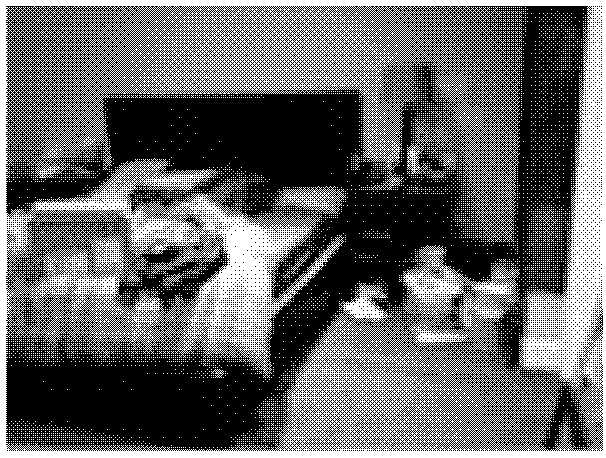
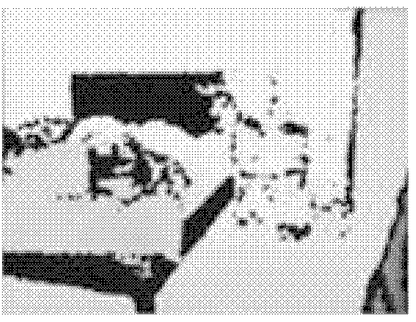
[0023] In order to better understand the technical solution of the present invention, further description will be made below in conjunction with the accompanying drawings. Figure 1 shows an example of depth estimation, where the input is Figure 1a For the monocular image shown, it is required to estimate Figure 1b Depth of scene shown.

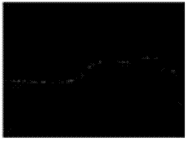
[0024] Step 1: Construct a reference depth map and a residual depth map based on the single-line laser. Figure 2a The known single-line laser information in Figure 1 is shown, and it can be seen that the single-line laser information is very sparse and limited. In order to densify the sparse single-line laser information, each laser point is stretched in the direction perpendicular to the ground in three-dimensional space to obtain a reference depth plane perpendicular to the ground. According to the calibration information of the monocular camera and the single-line laser, the reference depth plane obtained in three dimensions is corresp...


PUM


Abstract

The invention discloses a sparse laser observation-based image depth estimation method. The method proposes that monocular image-based depth dense reconstruction is realized by utilizing sparse observation of single-line laser or multi-line laser. A deep neural network is trained in a mode of constructing a reference depth map and a residual error depth map, and sparse partial observation depth information is fully utilized. Compared with a method for performing depth estimation only by using a monocular image, the method provided by the invention has remarkable advantages.

Description

technical field [0001] The invention relates to the field of scene depth estimation, in particular to a scene dense depth estimation method based on monocular images and sparse lasers. Background technique [0002] Based on rich experience and continuous learning, human beings also have the ability to estimate the distance of objects in the image from monocular images, that is, the ability to estimate depth to a certain extent. In recent years, machine learning methods have also made remarkable progress in imitating the depth estimation ability of humans, especially data-driven deep learning techniques. This technique avoids the manual feature design process, learns features based on the original monocular RGB image, and outputs a prediction of the corresponding depth of the image. [0003] Eigen et al. first proposed deep learning-based monocular depth estimation. They constructed a two-stage depth estimation network. The first stage generates a rough estimate and the seco...

Claims


Application Information

Patent Timeline
IPC IPC(8): G06T7/55
CPCG06T2207/10004G06T2207/20081G06T2207/20084G06T2207/20221
Inventor 刘勇廖依伊王越
Owner ZHEJIANG UNIV
Why Eureka
Try Eureka